
Commonly-used diagnostic test device for vehicle

A diagnostic test and vehicle technology, applied in electrical testing/monitoring, digital transmission systems, electrical components, etc., can solve problems such as poor flexibility, inability to realize electrical signals, single function of testing equipment, etc., and achieve strong versatility

Active Publication Date: 2013-11-27
CHINA FIRST AUTOMOBILE
View PDF7 Cites 32 Cited by
  • Summary
  • Abstract
  • Description
  • Claims
  • Application Information

AI Technical Summary

Problems solved by technology

The increasingly complex electronic equipment not only brings challenges to the stability of the vehicle network, but also brings greater challenges to parameter calibration, software upgrades, and fault diagnosis and function updates during ECU R&D testing.
At present, the detection equipment has a single function, and the diagnosis and test functions are separated.
[0003] At present, the diagnostic equipment can only realize the fault diagnosis of a specific vehicle type, and the whole vehicle diagnostic equipment can only realize the fault diagnosis function, and cannot realize the direct collection of electrical signals, which makes it very difficult to analyze the cause of the fault and has poor flexibility.
For some non-bus signals, since there are no analog signal acquisition channels and I / O channels reserved, signal acquisition and analysis cannot be realized
[0004] The test equipment only conducts bus tests on some electronic control units of a specific vehicle type, lacks a system for testing the bus network of the entire vehicle, and most of the existing technologies only diagnose ECU systems with CAN bus or any type of K_Line interface Test, limited, not universal
At the same time, bus test equipment is generally only aimed at the data link layer and application layer of the bus network, but for the physical layer and network layer tests of the bus network, few diagnostic and test equipment can realize

Method used


Image

  • Commonly-used diagnostic test device for vehicle

Examples


Embodiment Construction

[0019] The present invention will be described in detail below with reference to the drawings and examples.

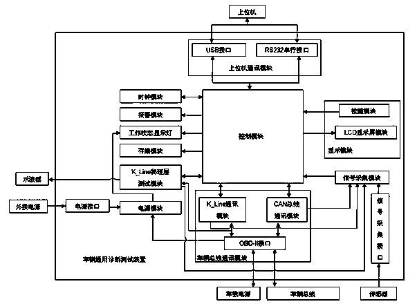
[0020] Such as figure 1 As shown, the vehicle general diagnostic test device of the present invention includes a control module for analyzing and processing data, a vehicle bus communication module connected to the control module and performing data exchange, a K_Line physical layer test module, a display module, and a control module connected to the host computer. The upper computer communication module and clock module, the signal acquisition module connected with the control module and transmitting data to the control module, the storage module connected with the control module, the working status display lamp and the alarm module, and the power supply module providing power for each module.

[0021] The 16-bit microprocessor of the control module adopts the M9S12XEP100MAL (112pin) single-chip microcomputer produced by Freescale Semiconductor Corporation. This sing...


PUM


Abstract

The invention discloses a commonly-used diagnostic test device for a vehicle. The commonly-used diagnostic test device comprises a control module, a vehicle bus communication module, a K-Line physical layer test module, a display module, an upper computer communication module, a clock module, a signal acquisition module, a storage module, a working state display lamp, an alarm module and a power module. The control module is used for analyzing and processing data, the vehicle bus communication module is connected with the control module and conducts data exchange, the upper computer communication module and the clock module are connected with an upper computer, the signal acquisition module is connected with the control module and transmits data to the control module, the storage module, the working state display lamp and the alarm module are connected with the control module, and the power module supplies power to all the modules. According to the commonly-used diagnostic test device, a performance test, a functional test and a diagnostic test can be conducted on a finished vehicle vehicle-mounted control unit, a diagnostic function test based on a bus network can be achieved, and a bus communication protocol and a diagnostic protocol are tested. The commonly-used diagnostic test device is high in universality, various vehicle models can be diagnosed, cross-platform vehicle models can be diagnosed, and the finished vehicle bus network can be diagnosed.

Description

technical field [0001] The invention relates to a vehicle diagnosis test device, in particular to a vehicle general diagnosis test device capable of diagnosing vehicle faults and testing a vehicle bus network. Background technique [0002] With the development of automobile technology, the degree of automobile electronics has become the most important technical measure for developing new models and improving automobile performance. The increasingly complex electronic equipment not only brings challenges to the stability of the vehicle network, but also brings greater challenges to parameter calibration, software upgrades, fault diagnosis and function updates during ECU R&D and testing. At present, the detection equipment has a single function, and the diagnosis and test functions are separated. [0003] At present, the diagnostic equipment can only realize the fault diagnosis of a specific vehicle type, and the vehicle diagnostic equipment can only realize the fault diagnos...

Claims


Application Information

Patent Timeline
IPC IPC(8): G05B23/02H04L12/26H04L29/06
Inventor 马如斌陈海君郭琳于健秋屈凡季德斌
Owner CHINA FIRST AUTOMOBILE
Learn More