Detection base of mobile terminal antenna

A mobile terminal antenna and pedestal technology, applied in the direction of the measuring device shell, etc., can solve the problems affecting the accuracy of radio frequency parameters, the influence of radio frequency parameter accuracy, and large electromagnetic interference of wires, so as to achieve good application prospects, improve detection accuracy, The effect of reducing electromagnetic interference

Inactive Publication Date: 2013-11-27
KUNSHAN FOR EASIER AUTOMATION TECH
View PDF0 Cites 2 Cited by
  • Summary
  • Abstract
  • Description
  • Claims
  • Application Information

AI Technical Summary

Problems solved by technology

[0002] With the rapid development of science and technology, handheld mobile terminals such as PAD, smart phones, etc. Most of them use the built-in mobile terminal antenna, and before using the mobile terminal antenna, it is necessary to test the radio frequency parameters of the mobile terminal antenna to check whether it meets the factory requirements. The entire testing process needs to be in a sealed resonant cavity. The detection base of the terminal antenna is engaged with the resonant cavity to form a sealed state. The probe set on the detection base is used to detect the radio frequency parameters, and the network analyzer is connected to the network analyzer through the wires to analyze the radio frequency parameters. However, due to the use of external wires, There will be large electromagnetic interference between the wires, which will affect the accuracy of radio frequency parameter detection, and the existing mobile terminal antenna is not fixed on the detection base with any fixing measures, which will cause displacement during the detection process and will also affect the The accuracy of radio frequency parameter detection will affect

Method used


Image

  • Detection base of mobile terminal antenna

Examples


Embodiment Construction

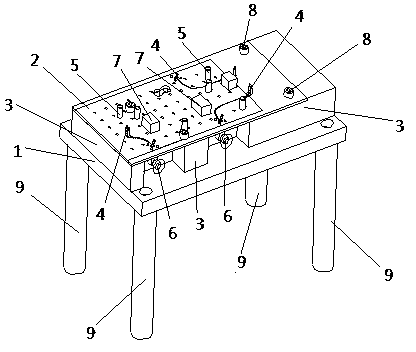
[0013] The present invention will be further described below in conjunction with the accompanying drawings.

[0014] like figure 1 As shown, a detection base of a mobile terminal antenna includes a substrate 1, a PWB board 2 and a backing board 3, the PWB board 2 is a commonly used printed circuit board, and the PWB board 2 is fixed on the top of the substrate 1 through the backing board 3. The board 2 is provided with a probe 4 for detecting the radio frequency parameters of the mobile terminal antenna. The probe 4 is located at the detection point of the mobile terminal antenna. The interface 6 is connected, and the SMA interface 6 is used to connect an external network analyzer. Here, the radio frequency parameter signal is transmitted through the wire printed in the PWB board 2. Compared with the traditional wire transmission, the electromagnetic interference is greatly reduced and the detection accuracy is improved. On the PWB board 2 There is a positioning post 5 for po...


PUM


Abstract

The invention discloses a detection base of a mobile terminal antenna. The detection base comprises a substrate, a PWB plate and a base plate; the PWB plate is fixed on the substrate through the base plate; the PWB plate is provided with a probe for detecting radio frequency parameters for the mobile terminal antenna; the probe is located at a detection point of the mobile terminal antenna; the PWB plate is further provided with a positioning column used for positioning the mobile terminal antenna; the probe is connected with an SMA interface located below the PWB plate through a wire printed inside the PWB plate; and the SMA interface is used for externally connecting a network analyzer. The detection base of the mobile terminal antenna is advantageous in favorable fixation, no interference on radio frequency signals of the mobile terminal antenna, improvement of detection accuracy, ingenious design and great application prospect.

Description

technical field [0001] The invention relates to the technical field of antenna detection, in particular to a detection base of a mobile terminal antenna. Background technique [0002] With the rapid development of science and technology, handheld mobile terminals such as PAD, smart phones, etc. Most of them use the built-in mobile terminal antenna, and before using the mobile terminal antenna, it is necessary to test the radio frequency parameters of the mobile terminal antenna to check whether it meets the factory requirements. The entire testing process needs to be in a sealed resonant cavity. The detection base of the terminal antenna is engaged with the resonant cavity to form a sealed state. The probe set on the detection base is used to detect the radio frequency parameters, and the network analyzer is connected to the network analyzer through the wires to analyze the radio frequency parameters. However, due to the use of external wires, There will be large electromag...

Claims


Application Information

Patent Timeline
Patent Type & Authority Applications(China)
IPC IPC(8): G01R1/04
Inventor 郭池洪操林徐丰
Owner KUNSHAN FOR EASIER AUTOMATION TECH
Why Eureka
Try Eureka