Transmission tensioning device

A technology of tensioning device and axial position, which is applied in the direction of transmission device, belt/chain/gear, mechanical equipment, etc. It can solve the problems of easy wear, tight half of the transmission belt, and inconvenience, so as to improve the service life and protect both sides. Even tension, fast and convenient installation and replacement

Active Publication Date: 2013-11-27
WUXI HONGYUAN ELECTROMECHANICAL TECH
View PDF8 Cites 0 Cited by
  • Summary
  • Abstract
  • Description
  • Claims
  • Application Information

AI Technical Summary

Problems solved by technology

[0003] 1. It is troublesome and inconvenient to change the running speed of the whole machine or replace the belt;
[0004] 2. Vibration will be generated when the motor is running at high speed, which will affect the operation performance of the whole machine;
[0005] 3. It is easy to cause half of the transmission belt to be tight and half to be loose;
[0006] 4. It is difficult to control the tension degree;
[0007] 5. It is easy to wear and tear, which reduces the service life of the transmission belt

Method used


Image

  • Transmission tensioning device
  • Transmission tensioning device

Examples


Embodiment 1

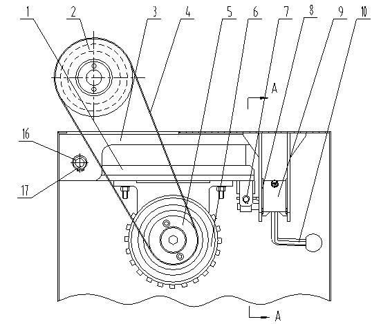
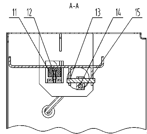
[0020] Embodiment 1: as figure 1 , 2 As shown, a transmission tensioning device includes a motor base 1, a pulley 2, a motor casing 3, a transmission belt 4, a motor pulley 5, a motor 6, a second retaining ring 7, a third retaining ring 8, and an eccentric shaft 9 , handle 10, shockproof pad 11, nut 12, shaft 13, pin shaft 14, slide block 15, first retaining ring 16 and fulcrum 17, one end of motor base 1 is connected with motor 6 casing 3 by fulcrum 17, and The motor base 1 can rotate around the support shaft 17, and the axial position of the support shaft 17 is determined by the first retaining ring 16; the other end of the motor base 1 has a shaft 13 passing through it horizontally, and the axial position of the shaft 13 is determined by the second retaining ring 7 Fixed, the shaft 13 is covered with a slider 15, the slider 15 is fixed on the shaft end edge of the eccentric shaft 9 through the pin shaft 14, the eccentric shaft 9 is fixed on the motor box 3 through the thir...


PUM


Abstract

The invention discloses a transmission tensioning device. The transmission tensioning device comprises a motor base, a motor casing, an eccentric shaft, a shaft, a sliding block and a fulcrum shaft; one end of the motor base is connected with the motor casing through the fulcrum shaft and rotates around the fulcrum shaft; the other end of the motor base and the shaft are fixed together; the sliding block which sleeves the shaft is fixed at the edge of the shaft end of the eccentric shaft; circular motion is performed on the sliding block along with rotation of the eccentric shaft and the sliding block slides on the shaft simultaneously. According to the transmission tensioning device, the traditional transmission design scheme of tensioning wheels and tensioning belts is cancelled, ahandle needs to be rotated only and the height difference produced by rotation of the eccentric shaft is utilized to raise the motor base and shorten the distance between a motor belt wheel and a belt wheel, so that the installation and replacement of a transmission belt is rapid and convenient; the gravity of a motor is utilized and the structure of the eccentric shaft, a pin shaft and the sliding block is adopted to tension the belt to perform transmission; a gear of the belt on the motor belt wheel can be conveniently adjusted and the operating speed of a machine can be adjusted without any tool.

Description

technical field [0001] The invention relates to a motor transmission device, in particular to a transmission tensioning device. Background technique [0002] At present, in the field of textile machinery design, most of them rely on the main motor to transmit power to each actuator through belt drive. The traditional or similar models of drive belt tensioning methods are all realized by installing a tensioning wheel on one side of the belt. , but for motors that require a high maximum delivery speed, or often need to change the position of the belt on the tower pulley to change the running speed of the whole machine, this tensioning method has the following disadvantages: [0003] 1. It is troublesome and inconvenient to change the running speed of the whole machine or replace the belt; [0004] 2. Vibration will be generated when the motor is running at high speed, which will affect the operation performance of the whole machine; [0005] 3. It is easy to cause half of th...

Claims


Application Information

Patent Timeline
Patent Type & Authority Applications(China)
IPC IPC(8): F16H7/14
Inventor 邓全娣
Owner WUXI HONGYUAN ELECTROMECHANICAL TECH
Why Eureka
Try Eureka