Device for condensing methane in rotating manner

A technology of biogas and condenser, which is applied in the direction of gas fuel, petroleum industry, fuel, etc., can solve the problems of low condensation efficiency and high air intake requirements of generator sets, achieve low operating costs, simplify biogas dehydration process, and save costs

Active Publication Date: 2014-12-10
ENERGY & ENVIRONMENT RES INST OF HEILONGJIANG PROVINCE
View PDF5 Cites 0 Cited by
  • Summary
  • Abstract
  • Description
  • Claims
  • Application Information

AI Technical Summary

Problems solved by technology

[0005] The purpose of the present invention is to solve the problem that the existing biogas dehydration methods mainly include the throttling expansion cooling dehydration method and the post-pressurization cooling method. Both methods require additional booster equipment, and the condenser must be installed at the lowest point of the pipeline. , resulting in low condensation efficiency, which cannot meet the high intake requirements of the generator set, and provides a biogas rotary condensation device

Method used


Image

  • Device for condensing methane in rotating manner
  • Device for condensing methane in rotating manner

Examples


specific Embodiment approach 1

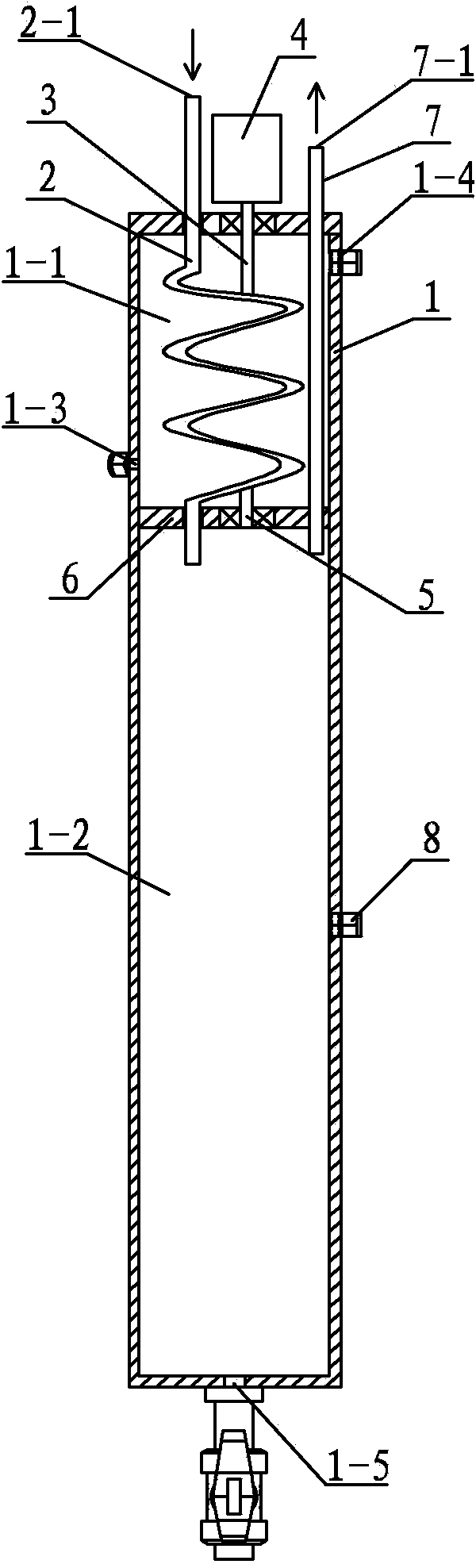
[0014] Specific implementation mode one: combine figure 1 and figure 2 Describe this embodiment. This embodiment includes a condenser 1, a screw shaft 2, a drive shaft 3, a motor 4, a driven shaft 5, a baffle 6 and a biogas output pipe 7. The condenser 1 is a cylindrical structure, and the baffle The plate 6 is horizontally arranged in the condenser 1, the condensate bin 1-1 is above the baffle 6, and the condensate collection bin 1-2 is below the baffle 6, and the screw shaft 2 is set in the condensate bin 1-2. 1, the upper end of the screw shaft 2 is the biogas inlet 2-1 and passes through the top of the condenser 1, the upper end of the screw shaft 2 passes through the baffle plate 6 and is located in the condensed water collection bin 1-2, and the driving shaft 3 is installed through a bearing On the top of the condenser 1, the input end of the driving shaft 3 is connected to the output end of the motor 4, the output end of the driving shaft 3 is connected to the screw s...

specific Embodiment approach 2

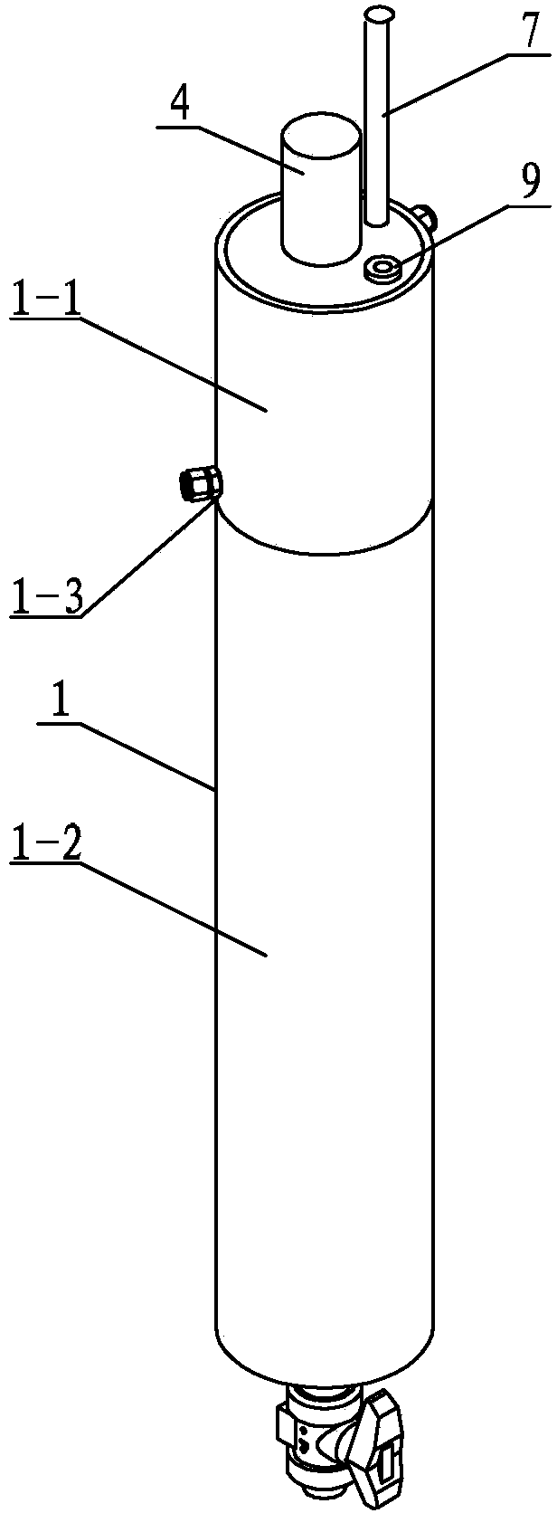
[0015] Specific implementation mode two: combination figure 1 This embodiment is described. The difference between this embodiment and the first embodiment is that it also adds a liquid level gauge 8, which is arranged on the side wall of the condenser 1 and located on the upper part of the condensed water collection bin 1-2. The liquid level gauge 8 is used to monitor the liquid level of the condensed water, and when the liquid level of the condensed water reaches a certain height, it will be discharged through the drain port 1-5 of the condenser. Other components and connections are the same as those in the first embodiment.

specific Embodiment approach 3

[0016] Specific implementation mode three: combination figure 2 Describe this embodiment, the difference between this embodiment and specific embodiment one is that it also adds an exhaust pipe 9, and the exhaust pipe 9 is arranged in the condensate tank 1-1, and the upper end of the exhaust pipe 9 passes through the condenser 1 The top of the exhaust pipe 9 passes through the baffle plate 6 and is located in the condensed water collection bin 1-2 at the lower end. When emergencies such as excessive pressure in the condensed water collection bin 1-2 occur, the exhaust pipe 9 is used to discharge the biogas in the condensed water collection bin 1-2. Other compositions and connections are the same as those in Embodiment 1 or 2.

[0017] Working principle of the present invention:

[0018] The condensate enters the condensate bin 1-1 from the condensate inlet 1-3 and fills up the condensate bin, biogas enters the screw shaft 2 from the biogas inlet 2-1, starts the motor 4, and...


PUM


Abstract

The invention discloses a device for condensing methane in a rotating manner, relates to a condensing device, and solves the problems that the existing methane dehydration methods mainly refer to a throttling expansion cooling dehydration method and a pressurizing-after cooling device, and in the two method, the condensation efficiency is low, and the high air inlet requirement of a generator set is not met. The device disclosed by the invention is characterized in that a condensing liquid bin is arranged above a baffle, a condensing water collecting bin is arranged below the baffle, the upper end of a spiral shaft is provided with a methane inlet which can pass through the top of a condenser, and the lower end of the spiral shaft passes through the baffle and is positioned in the condensing water collecting bin; the input end of a driving shaft is connected with the output end of a motor, the output end of the driving shaft is connected with a spiral pipe, and a driven shaft is connected with the spiral pipe; the upper end of a methane output pipe is provided with a methane outlet and can pass through the top of the condenser, the lower end of the methane output pip passes through the baffle and is positioned in the condensing water collecting bin, a condensing liquid inlet is formed in the lower part the condensing liquid bin, a condensing liquid outlet is formed in the upper part of the condensing liquid bin, and the lower end of the condenser is provided with a condenser water discharging port. The device provided by the invention is suitable for being used in a methane power generation technology of a large-scale methane project.

Description

technical field [0001] The invention relates to a condensation device, in particular to a biogas rotary condensation device. Background technique [0002] The biogas power generation project is a system project that takes anaerobic digestion as the core technology, forms terminal products with biogas power generation, and integrates manure treatment, biogas production and power generation, and biogas resource utilization. However, due to the high requirements of biogas generator sets on the quality of biogas, especially in cold regions such as Heilongjiang, the power generation cost and power generation effect of biogas power generation projects cannot be well guaranteed. [0003] The main components of biogas are methane and carbon dioxide, and its calorific value is about 20-25MJ / m 3 . In the biogas project, the temperature of the biogas produced is different depending on the process, mostly around 30°C and 50°C, and contains a large amount of water vapor, which will cau...

Claims


Application Information

Patent Timeline
Patent Type & Authority Patents(China)
IPC IPC(8): C10L3/10
Inventor 徐晓秋刘伟王欣王志成刘旭丹
Owner ENERGY & ENVIRONMENT RES INST OF HEILONGJIANG PROVINCE
Why Eureka
Try Eureka