Clamping tool for machining eccentric shafts
What is Al technical title?
Al technical title is built by PatSnap Al team. It summarizes the technical point description of the patent document.
A technology for clamping tooling and eccentric shafts, which is applied in metal processing equipment, metal processing machine parts, clamping, etc., can solve the problems of low productivity and inability to meet the needs of parts processing, and achieve low manufacturing cost, convenient maintenance, The effect of long service life
Active Publication Date: 2016-07-13
三和机电股份有限公司
View PDF6 Cites 0 Cited by
Summary
Abstract
Description
Claims
Application Information
AI Technical Summary
This helps you quickly interpret patents by identifying the three key elements:
Problems solved by technology
Method used
Benefits of technology
Problems solved by technology
[0002] The clamping tool of the lathe usually refers to the device for clamping the workpiece, such as the chuck on the lathe. In actual production, the general clamping tool often cannot meet the needs of various parts processing; or because of low productivity, it must be used. Appropriate improvement of the fixture; or due to the different shape of the workpiece, processing requirements, etc., a special fixture must be specially designed and manufactured to meet the actual needs of production
Method used
Image
Click on the blue label to locate the original text in one second.
Reading with bidirectional positioning of images and text.
Examples
Embodiment 1
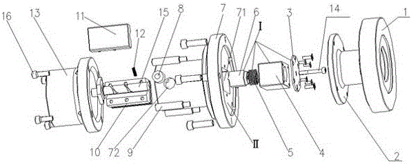
[0019] see Figure 1 to Figure 3 , the clamping tool for processing eccentric shafts according to the present invention includes a connecting plate 1, a tensioning plate 2, a fixing plate 3, a positioning sleeve 4, a spring 5, a positioning block 6, a mold shell 7, a pressing column 8, a tensioning Rod 9, V-shaped block 10, pressing plate 11, pressing plate spring 12 and pressing sleeve 13, described connecting plate 1, tensioning plate 2, formwork 7 and pressing sleeve 13 are installed coaxially successively.
[0020] The positioning sleeve 4 is provided with a through cavity, the positioning block 6, the spring 5, the positioning sleeve 4, and the fixing plate 3 are assembled and installed in sequence, the spring 5 is arranged in the cavity of the positioning sleeve 4, and one end of the spring 5 is against the fixing plate 3. The other end is against the positioning block 6, the positioning sleeve 4 is fixedly connected with the fixing plate 3, the bolt 14 passes through th...
PUM
Abstract
The invention relates to a clamping tool for machining eccentric shafts. The clamping tool comprises a connecting plate, a tensioning plate, a fixing plate, a location sleeve, a spring, a location block, a die shell, a pressing column, a tensioning rod, a V-type block, a pressing plate, a pressing plate spring and a pressing sleeve. The connecting plate, the tensioning plate, the die shell and the pressing sleeve are sequentially and coaxially installed, a penetrated cavity is formed in the location sleeve, the location block, the spring, the location sleeve and the fixing plate are sequentially installed in a combined mode, the spring is arranged in the cavity of the location sleeve, one end of the spring abuts against the fixing plate, the other end of the spring abuts against the location block, the location sleeve is fixedly connected with the fixing plate, and a bolt penetrates through the fixing plate, the spring and the location sleeve to be in threaded connection with the location block. The clamping tool can be connected with hydraulic or starting devices, the automation level is improved, and the time for machining workpieces and assembling and disassembling the workpieces is greatly shortened. The V-type block and the pressing plate serve as clamps, therefore, work for assembling the workpieces and converting a work position can be greatly simplified, the labor strength is reduced, and the safety production can be guaranteed.
Description
technical field [0001] The invention relates to a clamping tool for processing an eccentric shaft, which belongs to the field of mechanical manufacturing. Background technique [0002] The clamping tool of the lathe usually refers to the device for clamping the workpiece, such as the chuck on the lathe. In actual production, the general clamping tool often cannot meet the needs of various parts processing; or because of low productivity, it must be used. Appropriate improvement of the fixture; or due to the different shape of the workpiece, processing requirements, etc., a special fixture must be specially designed and manufactured to meet the actual needs of production. Contents of the invention [0003] The purpose of the present invention is to overcome the above-mentioned deficiencies in the prior art, and provide a clamping tool for machining eccentric shafts with reasonable structural design, which can effectively improve production efficiency, reduce labor intensity...
Claims
Application Information
Patent Timeline
Application Date:The date an application was filed.
Publication Date:The date a patent or application was officially published.
First Publication Date:The earliest publication date of a patent with the same application number.
Issue Date:Publication date of the patent grant document.
PCT Entry Date:The Entry date of PCT National Phase.
Estimated Expiry Date:The statutory expiry date of a patent right according to the Patent Law, and it is the longest term of protection that the patent right can achieve without the termination of the patent right due to other reasons(Term extension factor has been taken into account ).
Invalid Date:Actual expiry date is based on effective date or publication date of legal transaction data of invalid patent.