Leakage inductance energy absorption circuit for Flyback converters

A leakage inductance energy absorption and converter technology, applied in the direction of adjusting electrical variables, converting DC power input to DC power output, instruments, etc., can solve the problems of damage to semiconductor components, complexity, and high circuit complexity, and achieve stable output voltage , Eliminate voltage spikes, suppress surge current effects

Inactive Publication Date: 2013-11-20
SHENZHEN JINGFUYUAN TECH
View PDF0 Cites 7 Cited by
  • Summary
  • Abstract
  • Description
  • Claims
  • Application Information

AI Technical Summary

Problems solved by technology

On the other hand, the voltage surge of the switch off and the voltage surge of the diode reverse recovery may damage the semiconductor components and generate noise at the same time
[0004] There are three kinds of traditional leakage inductance energy absorbing circuits. The first is the RCD lossy leakage inductance absorbing circuit. This circuit transfers the leakage inductance energy to the resistor for consumption, which can eliminate voltage spikes, but the efficiency of the system is low; the second is The second is an active clamping circuit, which can not only eliminate voltage spikes and improve system efficiency, but also achieve soft switching, but the circuit is more complex; the third is a passive clamping circuit, this The circuit can also eliminate voltage spikes and improve system efficiency, but in this way, in the closed-loop design, because the potentials of the two ports of the secondary output are floating relative to the power ground of the primary side, there will be a certain degree of uncertainty in the design. complexity, and can lead to loss of the original isolation performance of the transformer

Method used


Image

  • Leakage inductance energy absorption circuit for Flyback converters
  • Leakage inductance energy absorption circuit for Flyback converters
  • Leakage inductance energy absorption circuit for Flyback converters

Examples


Embodiment Construction

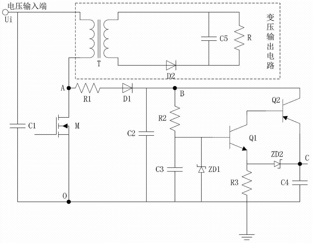
[0019] refer to figure 1 , a leakage inductance energy absorbing circuit for a Flyback converter of the present invention, comprising a voltage input terminal, a first capacitor C1, a second capacitor C2, a third capacitor C3, a fourth capacitor C4, a switch tube M, and a first transistor Q1 , the second transistor Q2, the first resistor R1, the second resistor R2, the third resistor R3, the first diode D1, the first voltage regulator transistor ZD1, the second voltage regulator transistor ZD2 and the variable voltage output circuit, the voltage The input terminal is connected to the ground through the first capacitor C1, the voltage input terminal is connected to the first input terminal of the variable voltage output circuit, the second input terminal of the variable voltage output circuit is connected to the drain of the switch tube M, and the voltage input terminal is connected to the drain of the switch tube M. The drain of the switch tube M is connected to the positive e...


PUM


Abstract

A leakage inductance energy absorption circuit for Flyback converters, which is disclosed by the invention, can effectively absorb the energy accumulated in parasitic inducers and clamp switching voltage, consequently, surge current can be inhibited, the effect of eliminating the voltage peak of a main switch can be effectively realized, the efficiency of a system can be greatly increased as well while the temperature rise of the main switch can be decreased, and moreover, a stable output voltage can be obtained by means of the leakage inductance energy absorption circuit. The invention as the leakage inductance energy absorption circuit for Flyback converters can be widely applied in power supply products.

Description

technical field [0001] The invention relates to the field of electronic circuits, in particular to a leakage inductance energy absorbing circuit for a Flyback converter. Background technique [0002] Flyback converters are commonly known as single-ended flyback DC-DC converters, also known as flyback Flyback converters, or Buck-Boost converters. The Flyback converter circuit is derived from the Buck-Boost circuit using the coupling function of magnetic components. Come. During the turn-on period of the main switch tube of the Flyback converter, the circuit only stores and does not transfer energy, and only transfers energy to the load when the main switch tube is turned off. [0003] In a switching power supply, most of the main components are parasitic inductance and capacitance. The parasitic capacitance is generally connected in parallel with the switching element or diode, and the parasitic inductance is usually connected in series with it. Due to the effects of these ...

Claims


Application Information

Patent Timeline
IPC IPC(8): H02M3/335
Inventor 尹惊云陈恒留
Owner SHENZHEN JINGFUYUAN TECH
Why Eureka
Try Eureka