
Method for achieving laser radar scene simulation on basis of GPU programming

A laser radar and scene simulation technology, applied in image data processing, special data processing applications, instruments, etc., can solve the problems of not establishing, limiting the authenticity of the model, and not establishing a real and reliable scene, so as to achieve a high sense of reality and satisfy The effect of real-time requirements

Active Publication Date: 2013-11-20
XIDIAN UNIV
View PDF2 Cites 22 Cited by
  • Summary
  • Abstract
  • Description
  • Claims
  • Application Information

AI Technical Summary

Problems solved by technology

[0003] Wang Qi of Harbin Institute of Technology established a hardware-in-the-loop simulation system for heterodyne imaging lidar. The simulation target scene library model is based on the assumption that the target model is a non-absorbing ideal Lambertian reflector, which limits the authenticity of the model; Xi'an Electronics Wu Zhensen from the University of Science and Technology established the relationship between the lidar transceiver system, target scattering, transmission effects and other factors and the characteristics of the lidar three-dimensional image, and simulated the target lidar three-dimensional imaging, which can truly represent the target lidar echo wave performance, but no real-time computing scenarios have been established
[0004] It can be seen that the domestic technology of lidar scene simulation is still relatively rough, and no real, reliable and dynamically displayed scene has been established, which will affect the efficiency of detection and guidance.

Method used


Image

  • Method for achieving laser radar scene simulation on basis of GPU programming
  • Method for achieving laser radar scene simulation on basis of GPU programming
  • Method for achieving laser radar scene simulation on basis of GPU programming

Examples


Embodiment Construction

[0016] refer to figure 1 , the specific implementation process of the present invention is as follows:

[0017] Step 1. Import the 3D model generated by the 3D model generation software 3DMAX into the object-oriented image rendering engine OGRE, and obtain the position and normal information of each vertex of the 3D model in the vertex program.

[0018] Step 2, generate scene texture file

[0019] 2a) Obtain the parameters of the three-dimensional model material through experiments or measuring instruments, and the normal incidence reflectance C λ , roughness factor r and isotropy factor p;

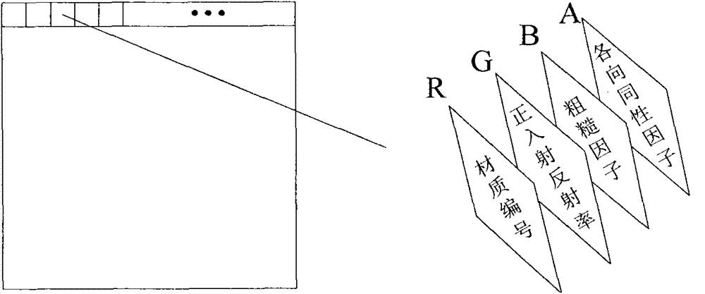
[0020] 2b) The texture of visible light is divided into different materials, and different materials are given the corresponding normal incidence reflectance C λ , roughness factor r and isotropy factor p, saved as a data texture in DDS format, the way to save the texture is as follows figure 2 As shown, the material number is stored in the R channel of the texture array, the normal ...


PUM


Abstract

The invention discloses a method for achieving laser radar scene simulation on the basis of GPU programming. The method mainly overcomes the defect that in the prior art, the physical reality sense of laser radar effect simulation is poor, so that dynamic rendering imaging cannot be performed. The method includes the steps of importing a three-dimensional model into a program, obtaining the position and normal information of each peak, obtaining parameters required for calculating a BRDF by means of experiments or instrument measurement, saving material type labels, normal incidence reflectivity, rough factors and isotropic factors into DDS data texture, sampling the data texture in a fragment program, obtaining the normal incidence reflectivity, the rough factors and the isotropic factors of different positions, combining the positions and the normal information of all peaks of the three-dimensional model, calculating laser luminance values of the different positions in a scene in the laser receiver direction according to a reflection model of the BRDF, and quantizing the laser luminance values into 8-bit gray values for displaying. The method can achieve dynamic imaging, is strong in reality sense, and can be applied to laser guidance and target detection.

Description

technical field [0001] The invention belongs to the technical field of computer simulation, and relates to a laser radar scene simulation method, specifically a method for realizing laser radar scene simulation based on a programmable graphics processing unit GPU programming, which can be used for target detection and missile guidance. Background technique [0002] With the development of lasers and detection components, lidar systems play an increasingly important role in military applications such as missile guidance and target detection. There are two methods for the study of lidar imaging: one is to use lidar to measure different targets in different backgrounds, but this requires a lot of manpower and material resources, and is restricted by meteorological factors. It is greatly affected by factors such as geographical environment and climatic conditions; another method is to simulate the lidar scene under different backgrounds and different targets through the lidar sc...

Claims


Application Information

Patent Timeline
Patent Type & Authority Applications(China)
IPC IPC(8): G06F17/50G06T19/00
Inventor 张建奇黄曦田利敏柴国贝王晓蕊
Owner XIDIAN UNIV
Learn More