
Bath water waste heat recoverer

A waste heat recovery, heat exchanger technology, used in heat exchanger types, indirect heat exchangers, lighting and heating equipment, etc.

Inactive Publication Date: 2013-11-20
中山天立卫厨有限公司
View PDF4 Cites 2 Cited by
  • Summary
  • Abstract
  • Description
  • Claims
  • Application Information

AI Technical Summary

Problems solved by technology

Existing problems: the water temperature in the upper part of the water tank is high and the water temperature in the lower part is low, and the heat exchanger cannot fully absorb the waste heat of the waste water

Method used


Image

  • Bath water waste heat recoverer
  • Bath water waste heat recoverer
  • Bath water waste heat recoverer

Examples


Embodiment Construction

[0032] The present invention will be further described below in conjunction with the accompanying drawings.

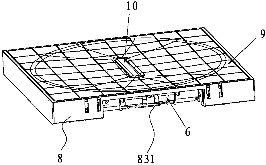
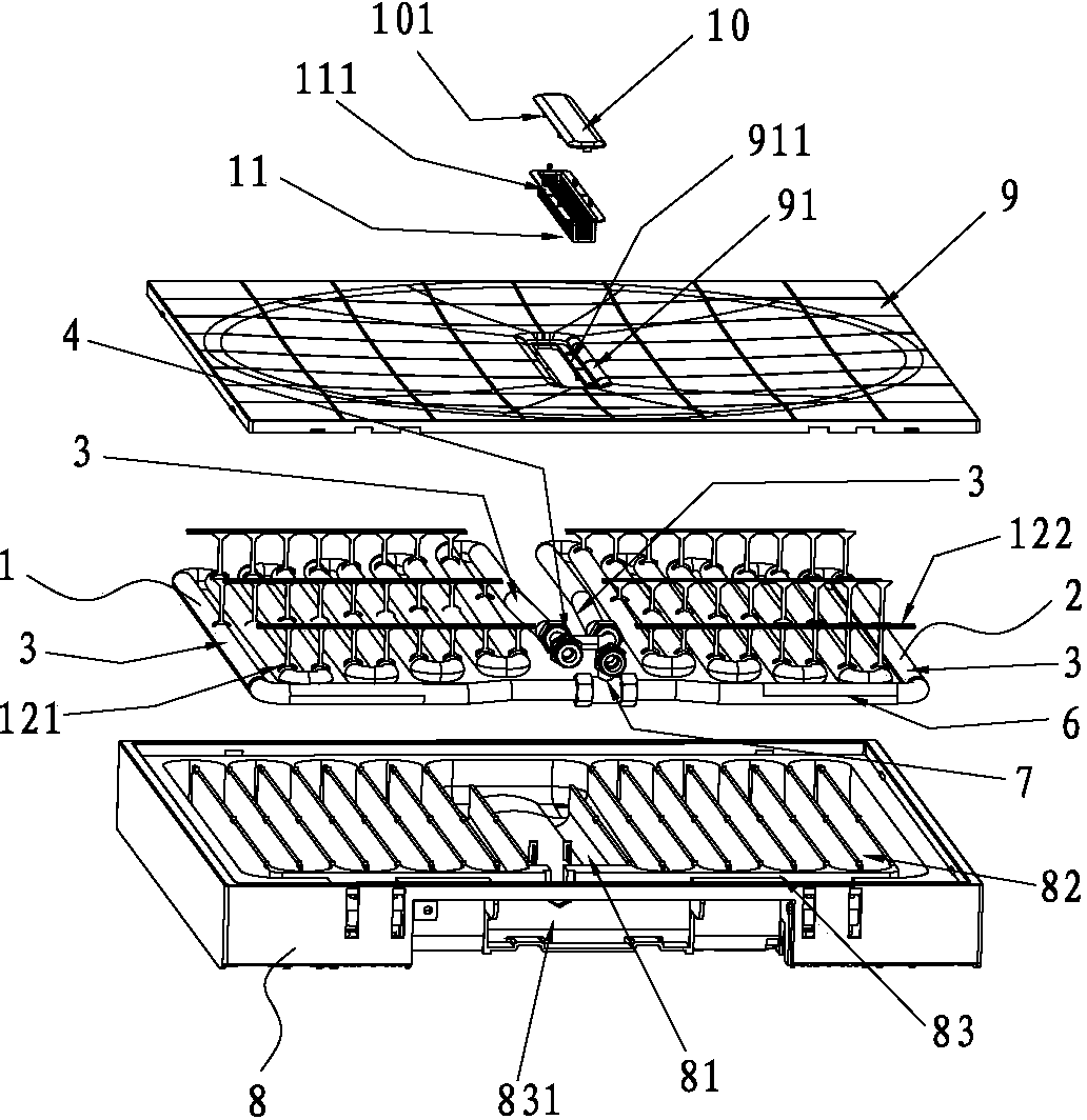
[0033] Such as figure 1 As shown in the figure, a waste heat recovery device for waste water includes a heat exchanger made of reciprocating bending of metal pipes and a plurality of heat exchange branch pipes connected in series. The heat exchanger is divided into a left heat exchanger 1 and a right heat exchanger 2 , the parallel structure of left and right heat exchangers; the heat exchange branch pipes 3 at the water outlets of the left and right heat exchangers 1 and 2 are adjacent and connected to the water outlet port 4, and the heat exchange branch pipes 3 at the water inlet end are connected through a connecting pipe 6 Connecting pipe 6 is provided with a water inlet port 7, and the water inlet port 7 is connected with the water source;

[0034] The heat exchange branch pipe is a corrugated heat exchange branch pipe.

[0035] It also includes a heat exchange...


PUM


Abstract

A bath water waste heat recoverer comprises a heat exchanger formed by a plurality of heat exchange branches manufactured by bending metal tubes. The heat exchanger is divided into a left heat exchanger and a right heat exchanger, the left heat exchanger and the right heat exchanger are of a parallel-connection structure, the heat exchange branches at the water outlet end of the left heat exchanger and the heat exchange branches at the water outlet end of the right heat exchanger are adjacent and connected with a water outlet, the heat exchange branches at the water inlet ends are communicated through a connecting pipe, a water inlet is formed in the connecting pipe, and the water inlet is communicated with a water source. The bath water waste heat recoverer further comprises a heat exchanger base, the heat exchange branches at the water outlet end of the left heat exchanger and the heat exchange branches at the water outlet end of the right heat exchanger are arranged in a central groove, other heat exchange branches of the left heat exchanger and other heat exchange branches of the right heat exchanger are embedded into a lateral water tank, and the connecting pipe is embedded into a communicating groove. By means of the structure, bath water can enter the central groove and pass through the lateral water tank to be drained out by the communicating groove, and the heat exchange branches of the left heat exchanger and the heat exchange branches of the right heat exchanger can absorb waste heat of the bath water repeatedly from the central groove, the lateral water tank and the communicating groove. Thus, the heat absorbing effect is good, and waste heat can be fully utilized.

Description

technical field [0001] The invention relates to a wastewater waste heat heat exchange device, in particular to a bath water waste heat recovery device. Background technique [0002] The utility model relates to a waste heat recovery device for waste water, which comprises a heat exchanger and a water tank formed by reciprocating bending of metal pipes and a plurality of heat exchange branch pipes connected in series, and the heat exchanger is immersed in the water tank. There are problems: the water temperature in the upper part of the water tank is high, and the water temperature in the lower part is low, and the heat exchanger cannot fully absorb the waste heat of the waste water. Contents of the invention [0003] The purpose of the present invention is to provide a recovery device for waste heat of bath water, which can make full use of waste heat, connect double circuits in parallel to reduce the drop, and have no stagnant water. [0004] The purpose of the present i...

Claims


Application Information

Patent Timeline
IPC IPC(8): F28D7/08
Inventor 谭文胜
Owner 中山天立卫厨有限公司
Learn More