
Layered electro-osmotic sludge dehydration device and using method thereof

A dehydration device and sludge technology, applied in the direction of dehydration/drying/concentrated sludge treatment, etc., can solve the problems of reduced service life, uneven pressure distribution, high energy consumption of sludge electroosmotic dehydration, and prevent secondary pollution , Obvious economic benefits, large amount of one-time processing effect

Inactive Publication Date: 2013-11-20
HOHAI UNIV
View PDF3 Cites 20 Cited by
  • Summary
  • Abstract
  • Description
  • Claims
  • Application Information

AI Technical Summary

Problems solved by technology

Chinese patent (publication number: CN 202543020 U) discloses a sludge dehydration and granulation device with synergistic effects of ring electric field and pressure. The problem of low energy consumption, the combination of electroosmotic dewatering and mechanical pressure filtration dewatering, there are insufficient sludge electroosmotic dehydration, uneven pressure distribution, high energy consumption, etc.; one of the reasons for the high energy consumption of sludge electroosmotic dehydration is Metal electrodes are used, and the corrosion of the metal electrodes seriously reduces the service life while increasing the contact resistance of the electrodes. The Chinese patent (publication number: CN 102720182 A) discloses a conductive plastic drainage plate that can play the role of drainage. At the same time, the corrosion of the electrode in the electroosmotic process is avoided, but the conductive plastic drainage board is difficult to recycle after use, and it is easy to be brittle during use.

Method used


Image

  • Layered electro-osmotic sludge dehydration device and using method thereof
  • Layered electro-osmotic sludge dehydration device and using method thereof
  • Layered electro-osmotic sludge dehydration device and using method thereof

Examples


Embodiment Construction

[0028] The present invention will be further described below in conjunction with the accompanying drawings and embodiments.

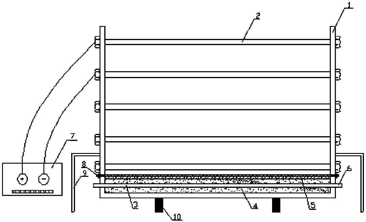
[0029] Refer to attached figure 1 , a kind of sludge layered electroosmotic dehydration device provided by the present invention is to lay a sand cushion 4 in the bottom end cover 10, bury the water filter pipe network 3 in the sand cushion, and the drainage main pipe leads to the outside of the cylinder and connects with the pump 6 , lay two layers of anti-filter geotextiles 5 on the surface of the sand cushion; arrange the electrodes 2 in a plum blossom shape along the depth direction of the cylinder, and fix the position through insulating nuts; use the flange 8 to connect the cylinder 1 and the bottom end cover 10 to form a cavity , a cylinder bracket 9 is arranged on the cylinder 1; sludge is injected along the side wall of the cylinder, and the electricity, 2 is connected to the power supply 7 in layers, always keeping the upper layer as the anode...


PUM


Abstract

The invention discloses a layered electro-osmotic sludge dehydration device and a using method thereof. The device is a cylinder with electrodes and a filter drainage medium layer, wherein the electrodes are quincuncially arranged in the cylinder in a layered manner; the filter drainage medium layer is arranged on a bottom end cover and consists of a sand cushion, a water filter pipe network and reverse filter geotechnical cloth; the bottom end cover is connected with the cylinder through a flange to form a cavity. The using method of the layered electro-osmotic sludge dehydration device comprises the following steps of: sequentially energizing the electrodes of two different layers at an electrode interval in a layer-by-layer or alternate manner so as to ensure that the electrode on the upper layer is positive while the electrode on the lower layer is negative all the time; and deeply dehydrating sludge under the action of a vertical electric field and a gravity field. The electrodes are conductive plastic pipes and are unlikely to be corroded. After electro-osmotic dehydration, the electrodes can be taken out and recycled with the filter drainage medium layer. The layered electro-osmotic sludge dehydration device is low in cost, simple in process and large in one-time treatment capacity; secondary environment pollution is avoided; the advantageous conditions are provided for subsequent treatment and resource utilization of sludge.

Description

technical field [0001] The invention relates to a sludge layered electroosmosis dewatering device and a use method thereof, belonging to the technical field of sludge dewatering. Background technique [0002] With the development of social economy and urbanization in our country, the generation and quantity of urban sewage are constantly increasing. Sludge is an accessory after sewage treatment. It is an extremely complex heterogeneous body composed of organic debris, bacterial cells, inorganic particles, and colloids. The amount of sludge usually accounts for 0.3% to 0.5% (volume) of the sewage volume or about 1% to 2% (quality) of the sewage treatment volume. A large amount of sludge is gradually becoming a source of environmental pollution. [0003] The water content of sludge can be as high as more than 99%, and the particles are finer, the specific gravity is smaller, and it is in a colloidal liquid state, so it is difficult to separate solids and liquids by sedimentat...

Claims


Application Information

Patent Timeline
IPC IPC(8): C02F11/12
Inventor 孙召花高明军余湘娟王振辉汤彬彬陈栋孙路东
Owner HOHAI UNIV
Learn More