Bus bar and method for manufacturing bus bar
A bus bar and bending direction technology, which is applied in the field of bus bar and bus bar manufacturing, can solve problems such as difficult to balance, and achieve the effects of suppressing deformation, improving productivity, and reducing man-hours
- Summary
- Abstract
- Description
- Claims
- Application Information
AI Technical Summary
Problems solved by technology
Method used
Image
Examples
no. 1 approach )
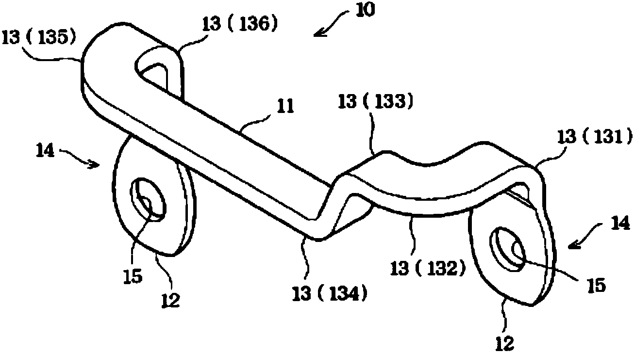
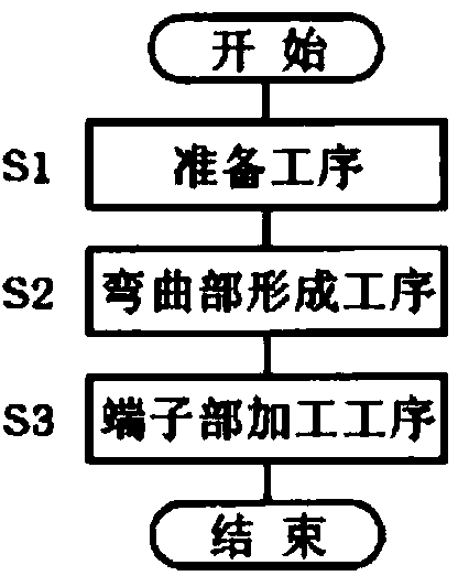
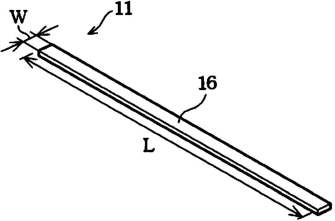
[0045] refer to Figure 1 to Figure 5 The bus bar and the method of manufacturing the bus bar according to the first embodiment will be described. like figure 1As shown, the bus bar 10 includes a body portion 11 and a terminal portion 12 . The body portion 11 is formed in a flat plate shape with a rectangular cross-sectional shape. The body part 11 is not limited to a rectangular cross-sectional shape, and may also be a rod-like structure with a circular cross-sectional shape, or a special-shaped cross-sectional shape such as an ellipse or an H shape. Furthermore, the body portion 11 has a plurality of bent portions 13 . In the bent portion 13 provided in the main body portion 11 , the bent portions 131 , 133 , 134 , and 136 are formed by a so-called planar bending method of bending the flat-shaped main body portion 11 in the plate thickness direction. In addition, the bent portions 132 and 135 are formed by a so-called seam bending method of bending in the plate width dir...
no. 2 Embodiment approach )
[0063] Next, a bus bar according to the second embodiment will be described with reference to FIGS. 6 and 7 . The bus bar in the second embodiment differs from the first embodiment in that the thickness of the terminal portion is compensated. The main body of the bus bar and the rough flow of the manufacturing method are the same as those of the first embodiment. Therefore, in the following description, the terminal portion of the bus bar will be mainly described.
[0064] When the thicknesses of the terminal portion and the body portion are different, that is, when there is a portion where the conduction cross-sectional area where current flows decreases, the resistance value increases in the high-voltage and high-frequency region at this portion. In this case, there is a possibility that heat may be generated at the portion where the conduction cross-sectional area is reduced. Therefore, in the present embodiment, the thickness of the terminal portion, which has become thi...
no. 3 Embodiment approach )
[0072] Next, a bus bar according to a third embodiment will be described with reference to FIGS. 8 and 9 . The bus bar in the third embodiment is different from that in the first embodiment in the process of forming the screw penetration holes in the terminal portions. In addition, the main body of the bus bar and the rough flow of the method of manufacturing the bus bar are the same as those of the first embodiment. Therefore, in the following description, the terminal portion of the bus bar will be mainly described.
[0073] In the bus bar according to the third embodiment, before performing the terminal part processing step, as Figure 8A As shown, the end portion 14 of the body portion 11 is bent into a ring shape. In the case of the present embodiment, the end portion 14 of the main body portion 11 is bent approximately 3 / 4 of a turn. Furthermore, the end portion 14 of the main body portion 11 is folded and stacked on the main body portion 11 . That is, the end portio...
PUM
 Abstract
Description
Claims
Application Information
 - R&D
- Intellectual Property
- Life Sciences
- Materials
- Tech Scout
- Unparalleled Data Quality
- Higher Quality Content
- 60% Fewer Hallucinations
Browse by: Latest US Patents, China's latest patents, Technical Efficacy Thesaurus, Application Domain, Technology Topic, Popular Technical Reports.
© 2025 PatSnap. All rights reserved.Legal|Privacy policy|Modern Slavery Act Transparency Statement|Sitemap|About US| Contact US: help@patsnap.com


