Controls for hybrid vehicles

A hybrid vehicle and control device technology, applied in hybrid vehicles, power devices, control devices, etc., can solve the problems of shifting shock, increase of input speed, and decrease of clutch torque capacity on the release side, etc., to achieve reliable transmission and suppress shifting shock Effect

Active Publication Date: 2016-01-06
TOYOTA JIDOSHA KK
View PDF3 Cites 0 Cited by
  • Summary
  • Abstract
  • Description
  • Claims
  • Application Information

AI Technical Summary

Problems solved by technology

In other words, the torque does not rise during engine start, and attempting to shift gears in this state causes the torque capacity of the clutch on the release side to decrease
Moreover, after the engine is started and the engine torque is generated, if the transmission input torque rises sharply with the completion of the engagement of the engine disconnect clutch, it is difficult to properly execute and increase the transmission torque in a state where the torque capacity of the release side clutch is reduced. Slope control of the input speed of the automatic transmission corresponding to the input torque, for example, there is a possibility that the input speed will rise and cause a shift shock
In this way, there is still room for improvement in the control method in the case of forming the starting request of the engine and the downshifting request of the automatic transmission during motor driving.
In addition, the above-mentioned problems are not well known, and no technology has been proposed to appropriately coordinate the timing of each control when the engine start control and the downshift control of the automatic transmission are executed overlappingly.

Method used


Image

  • Controls for hybrid vehicles
  • Controls for hybrid vehicles
  • Controls for hybrid vehicles

Examples


Embodiment 1

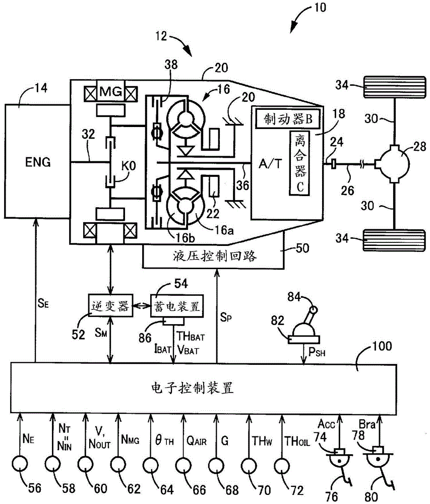
[0034] figure 1 It is a diagram illustrating a schematic structure of a power transmission path from the engine 14 to the driving wheels 34 constituting a hybrid vehicle 10 to which the present invention is applied (hereinafter, referred to as the vehicle 10 ), and is a diagram for realizing a driving force source for traveling. A diagram for explaining functions such as the output control of the engine 14 , the shift control of the automatic transmission 18 , the drive control of the electric motor MG, etc. are provided in the main part of the control system of the vehicle 10 .

[0035] figure 1 Among them, the power transmission device 12 for a vehicle (hereinafter referred to as the power transmission device 12 ) is installed in a transmission case 20 (hereinafter referred to as the case 20 ) as a non-rotating member mounted on the vehicle body by bolt fastening or the like, from The engine 14 side includes an engine disconnect clutch K0, an electric motor MG, a torque con...

Embodiment 2

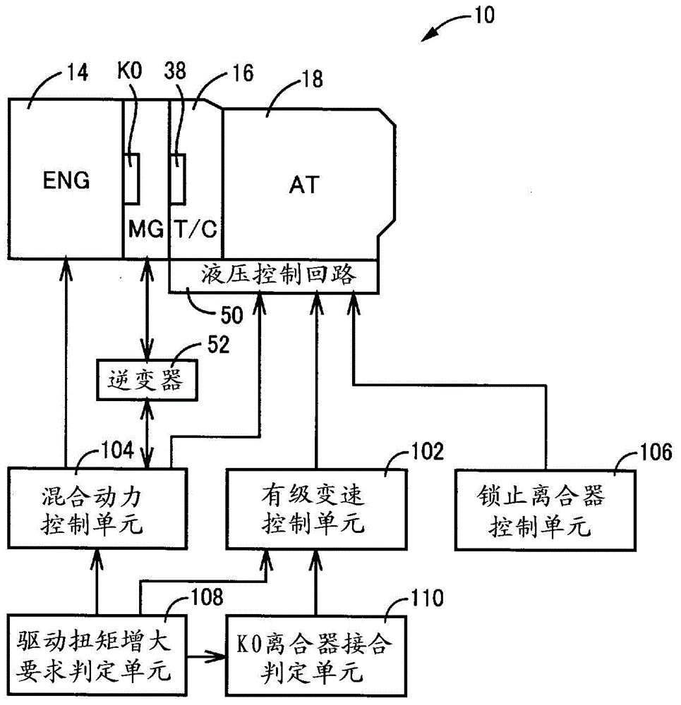
[0071] In the foregoing Embodiment 1, the K0 clutch engagement determination unit 110 is based on the actual engine speed N E and the actual motor speed N MG The speed difference ΔN K0 (=N MG -N E ) to determine whether the engine disconnection clutch K0 is engaged, or based on the actual transmission input speed N IN Synchronous speed with before shifting N IN The speed difference ΔN of b IN (=N IN -N IN b) It is determined whether the inertia phase of the downshifting process of the automatic transmission 18 is started, thereby determining whether or not the clutch K0 for engine disconnection has been engaged. In this way, electric signals transmitted from various sensors are used in the determination of the completion of engagement of the engine disconnect clutch K0. Therefore, there is a communication delay depending on the electrical signal used, and there is a possibility that a determination delay may occur. Therefore, it is preferable to perform the determinat...

Embodiment 3

[0082] In the aforementioned first embodiment, in order to suppress the occurrence of the shock at the time of engine start by the hybrid control unit 104, the lock-up clutch control unit 106 controls the lock-up clutch 38 of the torque converter 16 to a released or slipping state. However, as described above, when the downshift control of the automatic transmission 18 is executed in addition to the engine start control, when the engagement of the engine disconnection clutch K0 is completed, the automatic transmission 18 is made to function as a torque limiter, thereby suppressing Engagement shock (synchronous shock) of the clutch K0 for engine disconnection at the time of engine start. Therefore, when the downshift control of the automatic transmission 18 is executed in addition to the engine start control, the lock-up clutch 38 of the torque converter 16 may be controlled to be in the fully engaged state (lockup-on state). Thereby, the transmission loss accompanying bringing...


PUM


Abstract

In the case where the start control of the engine and the downshift control of the automatic transmission are executed in an overlapping manner, each control can be executed at an appropriate timing to suppress a shift shock. When there is a request to increase the drive torque during EV running, when the engine start control and the downshift control of the automatic transmission (18) are overlapped, starting from the completion of engagement of the engine disconnect clutch (K0), Since the transmission input rotation speed (NIN) starts to change to the post-shift synchronous rotation speed (NINa), the completion of the engagement of the engine disconnection clutch (K0) is captured as a rise in the transmission input torque (TAT), and the engine disconnection clutch ( After the engagement of K0) is completed, the downshift is performed in response to the increase of the transmission input torque (TAT) (inertial phase).

Description

technical field [0001] The present invention relates to a control device for a hybrid vehicle including an engine, an electric motor connected to the engine via a clutch, and an automatic transmission connected to the electric motor. Background technique [0002] There is known a hybrid vehicle which has: an engine and an electric motor as a driving force source for traveling; an engine disconnection clutch for disconnecting or connecting a power transmission path between the engine and the electric motor; An automatic transmission that transmits power from a drive source for travel to the drive wheels. Such a hybrid vehicle is described, for example, in Patent Documents 1-3. Normally, such a hybrid vehicle can perform motor travel in which the vehicle travels using only the electric motor as a driving force source for travel with the above-mentioned engine disconnect clutch released. Here, during the electric motor running, a switching request to switch to engine running ...

Claims


Application Information

Patent Timeline
Patent Type & Authority Patents(China)
IPC IPC(8): B60W10/115B60K6/48B60K6/547B60W10/02B60W10/06B60W30/19B60W30/192B60W20/00
CPCB60K6/48B60K6/547B60W10/02B60W10/06B60W10/115B60W20/40B60W30/19B60W30/192F16H61/0403B60W2710/1011B60Y2300/48B60Y2200/92F16H2312/20B60Y2300/18016B60W10/026B60W2050/0091B60W20/30Y10S903/902Y02T10/62B60W20/10
Inventor 小林宽英大坪秀显
Owner TOYOTA JIDOSHA KK
Why Eureka
Try Eureka