Control apparatus for vehicle

A technology for control devices and vehicles, applied in control devices, battery/fuel cell control devices, vehicle energy storage, etc., can solve problems such as reduction and speed change shocks, and achieve suppression of speed change shocks, high energy conversion efficiency, and improved energy conversion efficiency. Effect

Active Publication Date: 2013-11-13
AISIN AW CO LTD
View PDF1 Cites 0 Cited by
  • Summary
  • Abstract
  • Description
  • Claims
  • Application Information

AI Technical Summary

Problems solved by technology

In the case of regenerative operation of the rotating electrical machine, the relatively large negative torque output by the rotating electrical machine is transmitted to the input member, so if the above-mentioned normal clutch speed change is performed, the negative torque output by the rotating electrical machine will reduce the rotational speed of the input member. Large reductions for sharp changes, so the possibility of shift shock is high

Method used


Image

  • Control apparatus for vehicle
  • Control apparatus for vehicle
  • Control apparatus for vehicle

Examples


Embodiment Construction

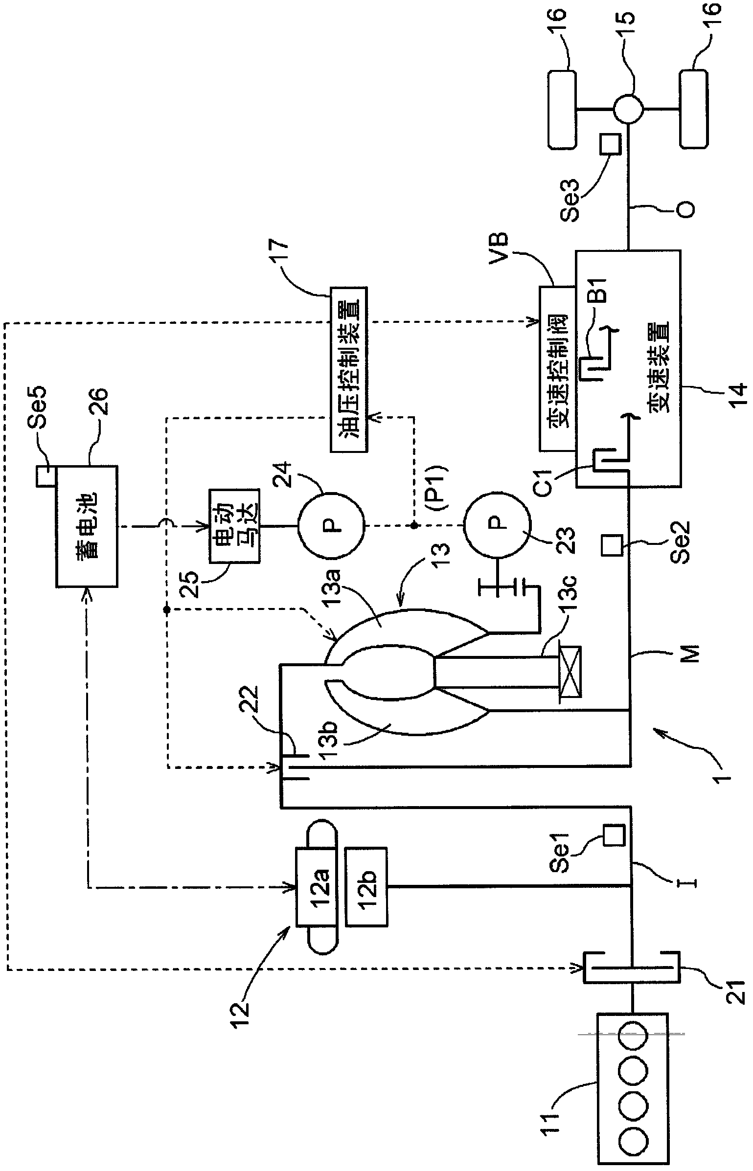
[0042] Embodiments of the present invention will be described with reference to the drawings. In this embodiment, a case where the vehicle control device of the present invention is applied to a vehicle drive device 1 for a hybrid vehicle will be described as an example. figure 1 It is a schematic diagram showing the configuration of a drive transmission system and a hydraulic control system of the vehicle drive device 1 according to the present embodiment. In the figure, a solid line indicates a transmission path of driving force, a dotted line indicates a supply path of hydraulic oil, and a dotted line indicates a supply path of electric power. As shown in the figure, the vehicle drive device 1 according to the present embodiment generally has a structure including an engine 11 and a rotating electric machine 12 as a drive force source, and the drive force of these drive force sources is transmitted to the drive system via a torque converter 13 and a transmission 14. to be ...


PUM


Abstract

To achieve both the suppression of the occurrence of any shift shock associated with the shifting operation and an improvement in the energy efficiency in a situation where a shift speed is switched to a shift speed with a smaller gear ratio when the accelerator pedal position of a vehicle is equal to or smaller than a prescribed value, there is provided a control apparatus for controlling a transmission apparatus that includes: an input member drivably connected to an engine and a rotating electrical machine; an output member; and a speed change mechanism in which a plurality of friction engagement elements are controlled to be engaged and released to switch a plurality of shift speeds, and that shifts the rotation speed of the input member at a gear ratio of each shift speed so as to output the shifted speed to the output member. When switching to a shift speed with a smaller gear ratio is carried out in an accelerator pedal light depression position state, a release-side oil pressure being a pressure of hydraulic oil on a to-be-released element, i.e., a release-side element, is reduced so as to cause the release-side element to slip. Such a slipping state is kept for the entire shifting phase that begins at a time point when the release-side element begins to slip and ends at another time point when a rotation speed, which is obtained by multiplying a rotation speed of the output member by the gear ratio after the switching of the shift speeds, and the rotation speed of the input member synchronize with each other.

Description

technical field [0001] The present invention relates to a vehicle control device for controlling a vehicle drive device comprising: an input member drivingly connected to an engine and a rotating electric machine; an output member; and a transmission device having a plurality of frictional engagements. A plurality of frictional engagement members are controlled to be engaged or disengaged, thereby switching between a plurality of shift speeds, thereby changing the speed of the rotational driving force of the input member at the speed ratio of each shift speed and outputting it to the output member. Background technique [0002] In recent years, a hybrid vehicle has been put into practical use, which uses both an engine and a rotary electric machine as a driving force source, thereby enabling a reduction in the fuel consumption rate of the engine and reduction in exhaust emissions. As an example of a vehicle drive device used in such a hybrid vehicle, for example, Patent Docu...

Claims


Application Information

Patent Timeline
Patent Type & Authority Patents(China)
IPC IPC(8): B60W10/08B60K6/48B60L11/18B60W10/02B60W10/115B60W30/18B60W30/19F16H61/06B60L50/16B60W10/10
CPCB60L2240/423B60W2540/10B60W2710/081B60W10/115B60W2520/10Y02T10/7044B60W2510/083B60W10/026B60W2510/244B60W2510/1015B60K6/48B60L2240/486Y02T10/7005B60W30/18127B60W20/00B60L2240/421Y02T10/705Y02T10/642B60L11/1861B60W30/19F16H61/061B60W10/08Y02T10/6221B60L58/12Y02T10/62Y02T10/64Y02T10/70Y02T10/72F16H61/06F16H59/14B60W20/30
Inventor 长谷重和上野博也津田耕平森山英二筒井洋
Owner AISIN AW CO LTD
Why Eureka
Try Eureka