A mobile phone terminal antenna
A mobile phone terminal and antenna technology, applied in the direction of antenna, antenna array, antenna support/installation device, etc., to achieve the effect of convenient adjustment and convenient antenna design
- Summary
- Abstract
- Description
- Claims
- Application Information
AI Technical Summary
Problems solved by technology
Method used
Image
Examples
Embodiment 1
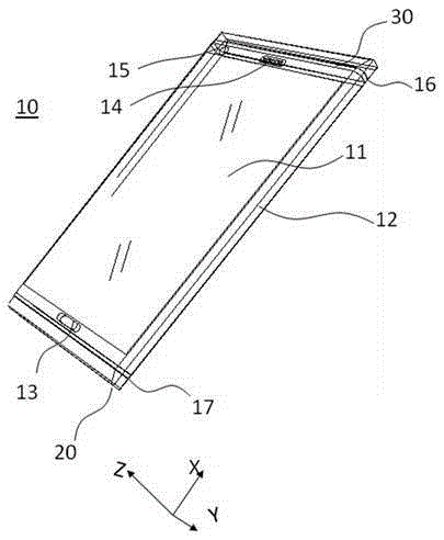
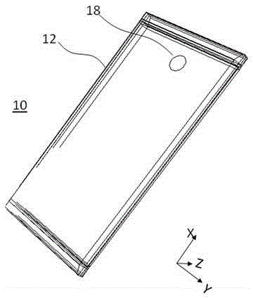
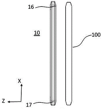
[0058] refer to Figure 1-12 , a mobile phone terminal antenna provided by the present invention is set on a mobile phone terminal 10 to transmit and receive wireless signals. The mobile phone terminal antenna includes a housing and an antenna part, the antenna part is arranged on the upper end and / or the lower end of the housing through an insulating medium, wherein the antenna part is in the shape of a cover with one end open, and the housing and the antenna part are connected to form the entire mobile phone terminal shell.
[0059] In this embodiment, the shell is a metal shell 12 with electrical conductivity. Of course, alloys can also be used as the material for the shell, such as stainless steel, magnesium-aluminum alloy, etc., which can be produced by milling, forging, etc., such as Figure 3-Figure 4 shape. The metal shell 12 has a polyhedron shape, including the left and right sides, the bottom surface and the front except for the area where the display screen is se...
Embodiment 2
[0072] refer to Figure 16, is an alternative embodiment of the present invention, and this embodiment is a modification made on the basis of Embodiment 1. Specifically, in this embodiment, the first circuit part is directly implemented by a grounding branch 28, which is located on the lower end surface of the connection between the metal shell 12 and the main antenna radiation body 22, and the grounding branch 28 is also connected to the metal shell 12 and main antenna 20. In this embodiment, the adjustment of the frequency of the first frequency band in which the main antenna 20 works is realized by the ground branch 28, and the position of the ground branch 28 is closer to the first feeding part 21 than the position of the inductance 27 in Embodiment 1, The frequency of the first frequency band is adjusted by adjusting the distance between the ground branch 28 and the first feeding part 21 . Except for the above improved parts, the rest of this embodiment is the same as t...
Embodiment 3
[0074] refer to Figure 17 and Figure 20 , is an alternative embodiment of the present invention. This embodiment is a modification made on the basis of Embodiment 1, so that the main antenna 20 can realize two low-frequency bands. Specifically, in this embodiment, the first circuit part is realized by using a switch circuit. The first circuit part 60 includes a first switch 61, a first input part 62, a first multi-channel inductance 67, a second multi-channel inductance 68 and a first data control line 64; one end of the first input part 62 is connected to the metal shell 12 and the main antenna radiation body 22, the other end is connected with multi-channel inductors 67 and 68; the first switch 61 has multiple input ports, and the multi-input ports are respectively connected to the first multi-channel inductor 67 and the second multi-channel inductor 68; the first switch 61 may have multiple output terminals, and its output terminals are directly connected to the ground,...
PUM
 Abstract
Description
Claims
Application Information
 - R&D
- Intellectual Property
- Life Sciences
- Materials
- Tech Scout
- Unparalleled Data Quality
- Higher Quality Content
- 60% Fewer Hallucinations
Browse by: Latest US Patents, China's latest patents, Technical Efficacy Thesaurus, Application Domain, Technology Topic, Popular Technical Reports.
© 2025 PatSnap. All rights reserved.Legal|Privacy policy|Modern Slavery Act Transparency Statement|Sitemap|About US| Contact US: help@patsnap.com


