
Magnetic resonance frequency and phase position double-encoding sampling method and image reconstruction method

A technology of frequency encoding and phase encoding, which is applied in the measurement of magnetic variables, measuring devices, instruments, etc., can solve the problems of speeding up the acquisition speed and lengthening the acquisition time, and achieves the effect of reducing the sampling time and accelerating the imaging speed.

Active Publication Date: 2013-11-13
SHANGHAI UNITED IMAGING HEALTHCARE
View PDF4 Cites 22 Cited by
  • Summary
  • Abstract
  • Description
  • Claims
  • Application Information

AI Technical Summary

Problems solved by technology

In the common method, the frequency encoding direction can speed up the acquisition speed and reduce the step size without affecting the overall acquisition time; but if the phase encoding direction reduces the step size, the acquisition time will be longer

Method used


Image

  • Magnetic resonance frequency and phase position double-encoding sampling method and image reconstruction method
  • Magnetic resonance frequency and phase position double-encoding sampling method and image reconstruction method
  • Magnetic resonance frequency and phase position double-encoding sampling method and image reconstruction method

Examples


Embodiment 1

[0056] The k-space acquisition sequence used in this embodiment is a sinusoidal acquisition sequence, and the tilt factor N is 2.

[0057] Figure 8 Schematic diagram of encoding gradient and ADC acquisition control for a sinusoidal acquisition sequence; Figure 9 It is a schematic diagram of a k-space acquisition trajectory using a sinusoidal acquisition sequence in the present invention.

[0058] Please refer to Figure 8 , G in the figure represents the gradient coil strength of magnetic resonance, where G PE Indicates the gradient of the phase encoding direction, G RO Indicates the gradient of the frequency encoding direction, (G Y Indicates the gradient in the Y direction, in general, the phase encoding gradient G PE is along the Y direction, G X Indicates the gradient in the X direction, in general, the frequency encoding gradient G RO along the X direction). ADC is an analog to digital converter, that is, a signal collector. Figure 8 The horizontal direction i...

Embodiment 2

[0072] The k-space acquisition sequence adopted in this embodiment is a reentrant acquisition sequence, and the tilt factor n is an integer greater than or equal to 4.

[0073] Figure 11 Schematic diagram of encoding gradient and ADC acquisition control for the reentry acquisition sequence; Figure 12 It is a schematic diagram of the k-space acquisition trajectory using the switchback acquisition sequence in Embodiment 2 of the present invention.

[0074] See Figure 11 , for the convenience of explanation, details such as RF pulse and layer selection gradient are omitted. The turn-back acquisition sequence provided in this embodiment is suitable for the case where the tilt factor is 2 or more. Figure 11 The turn-back acquisition sequence shown is characterized in that frequency encoding and phase encoding are added at the same time as k-space data acquisition; the phase encoding gradient is N times the frequency encoding gradient, and N is the ADC oversampling multiple; ...

Embodiment 3

[0080] The k-space acquisition sequence adopted in this embodiment is a rotary acquisition sequence, and the tilt factor N is an integer greater than 1.

[0081] Figure 14 Schematic diagram of encoding gradient and ADC acquisition control for the rotation acquisition sequence; Figure 15 It is a schematic diagram of the k-space acquisition trajectory using the rotary acquisition sequence in Embodiment 3 of the present invention.

[0082] See Figure 14 , for the convenience of illustration, Figure 14 Details such as layer selection gradient and RF pulse are omitted. The characteristic of this slewing acquisition sequence is that only one RF pulse excitation is required; after excitation, the gradient coil is used to adjust the initial entry point (such as Figure 15 60 marked in the point); phase encoding and frequency encoding are carried out at the same time, and at the same time by Figure 14 The "adapter sequence" in the box indicated by 51 and 52 in , performs posi...


PUM


Abstract

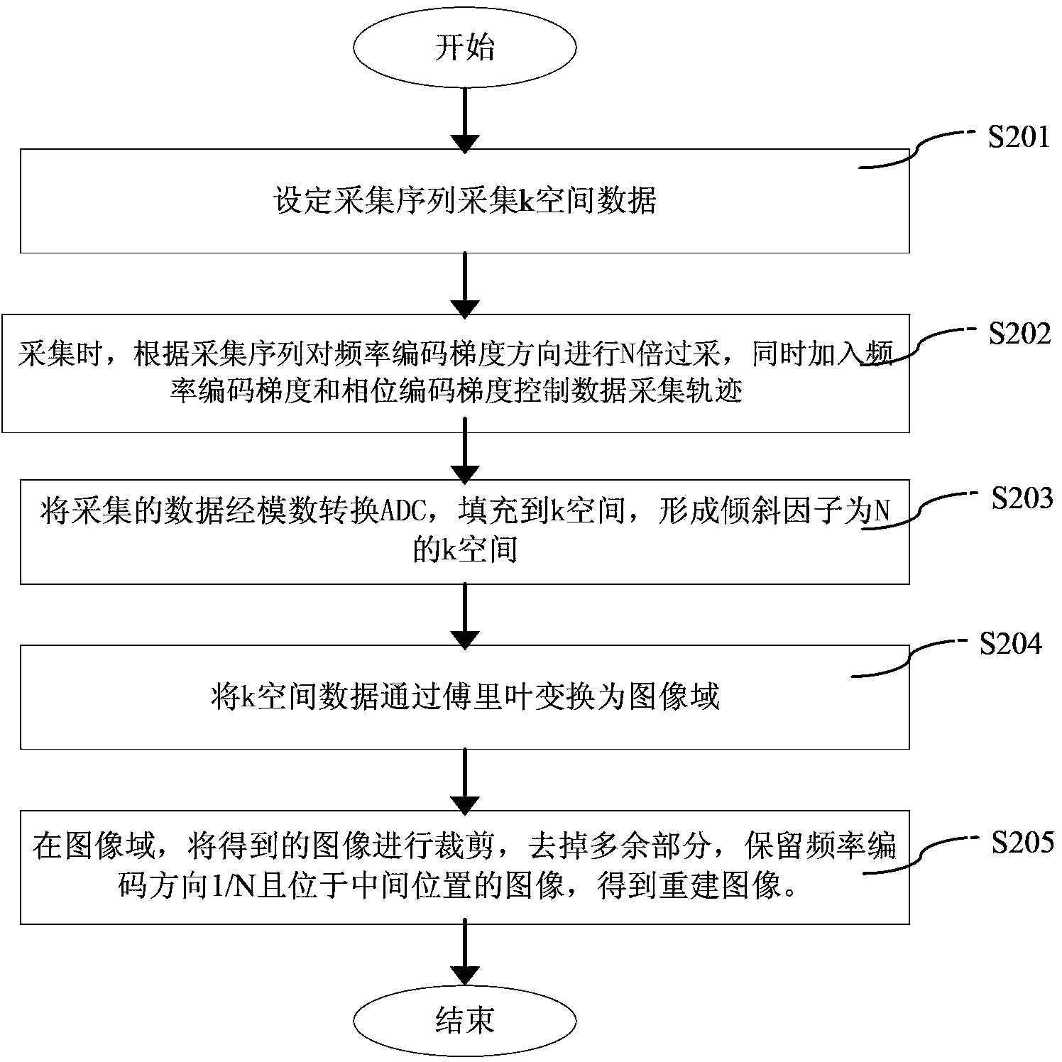
The invention discloses a magnetic resonance frequency and phase position double-encoding sampling method and an image reconstruction method. The sampling method comprises the following steps of (a) setting an acquisition sequence and acquiring k-space data; (b) performing N-time over-sampling to the frequency encoding gradient direction according to the acquisition sequence during acquisition and simultaneously adding frequency encoding gradient and phase position encoding gradient to control data acquisition tracks; (c) filling the data acquired in the step (b) into a k-space through an analog to digital converter (ADC) to form the k-space with an inclination factor N, wherein data points of the k-space are distributed along the frequency encoding gradient direction and the phase position encoding gradient direction in an inclined N*m rows*n columns mode, and (N-1) blank data points are filled between every two adjacent actually acquired data points in the frequency encoding direction and the phase position encoding direction, the N is an integer larger than 1, and the m and the n are positive integers. The magnetic resonance frequency and phase position double-encoding sampling method enables phase positions and frequency to be encoded simultaneously so as to control the k-space sampling tracks, enables acquisition times to be less than the acquisition s times of a traditional acquisition s mode, shortens the total acquisition time and enables reconstructed images not to have image artifacts basically.

Description

technical field [0001] The invention relates to magnetic resonance imaging technology, in particular to a frequency-phase double-coded sampling method and an image reconstruction method thereof. Background technique [0002] In the existing magnetic resonance imaging technology, the imaging method needs to fill up the k-space, and then perform Fourier transform on the filled k-space, and finally obtain a reconstructed image. The general data collection method is shown in Figure 1, in which, Figure 1a It is a schematic diagram of the gradient control of the readout direction and the ADC acquisition control after a certain phase encoding. The ADC is an analog-to-digital converter, that is, a signal collector. Figure 1b The solid point in ), the dotted arrow indicates the oversampled data (corresponding to Figure 1b The triangle point in ), the oversampled data is the data increased by increasing the ADC acquisition speed; Figure 1b The dot in the middle represents the co...

Claims


Application Information

Patent Timeline
Patent Type & Authority Applications(China)
IPC IPC(8): G01R33/561
Inventor 翟人宽
Owner SHANGHAI UNITED IMAGING HEALTHCARE
Learn More