Copying machining fixture

A profiling processing and fixture technology, applied in the direction of manufacturing tools, metal processing equipment, metal processing machinery parts, etc., can solve the problems of shaft scrapping, shaft deformation, difficult positioning, etc., and achieve the effect of improving quality and efficiency

Active Publication Date: 2013-11-13
太仓伟利达铭板科技有限公司
View PDF7 Cites 1 Cited by
  • Summary
  • Abstract
  • Description
  • Claims
  • Application Information

AI Technical Summary

Problems solved by technology

[0002]The profiling processing fixture is mainly to select the corresponding processing fixture according to the shape of the product. The system is connected, therefore, it is necessary to process the shaft, and the material of the shaft is mostly aluminum. The ordinary vise fixture cannot meet the processing requirements of the shaft, and it is easy to cause deformation of the shaft. At the same time, it is difficult to accurately position the surface of the shaft. Positioning, it is easy to cause the possibility of scrapping the entire shaft, which brings inconvenience to the processing of the shaft

Method used


Image

  • Copying machining fixture
  • Copying machining fixture

Examples


Embodiment Construction

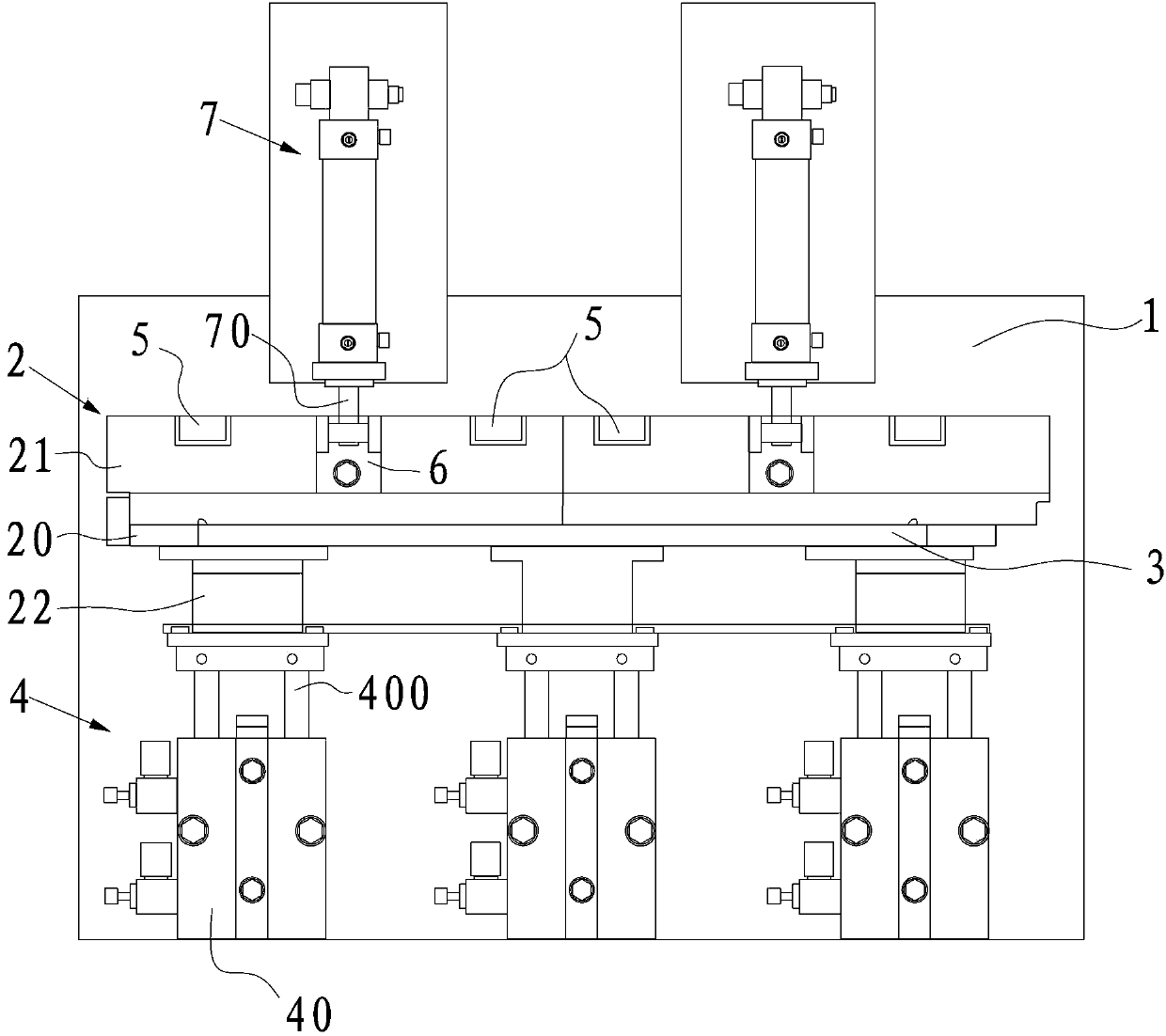
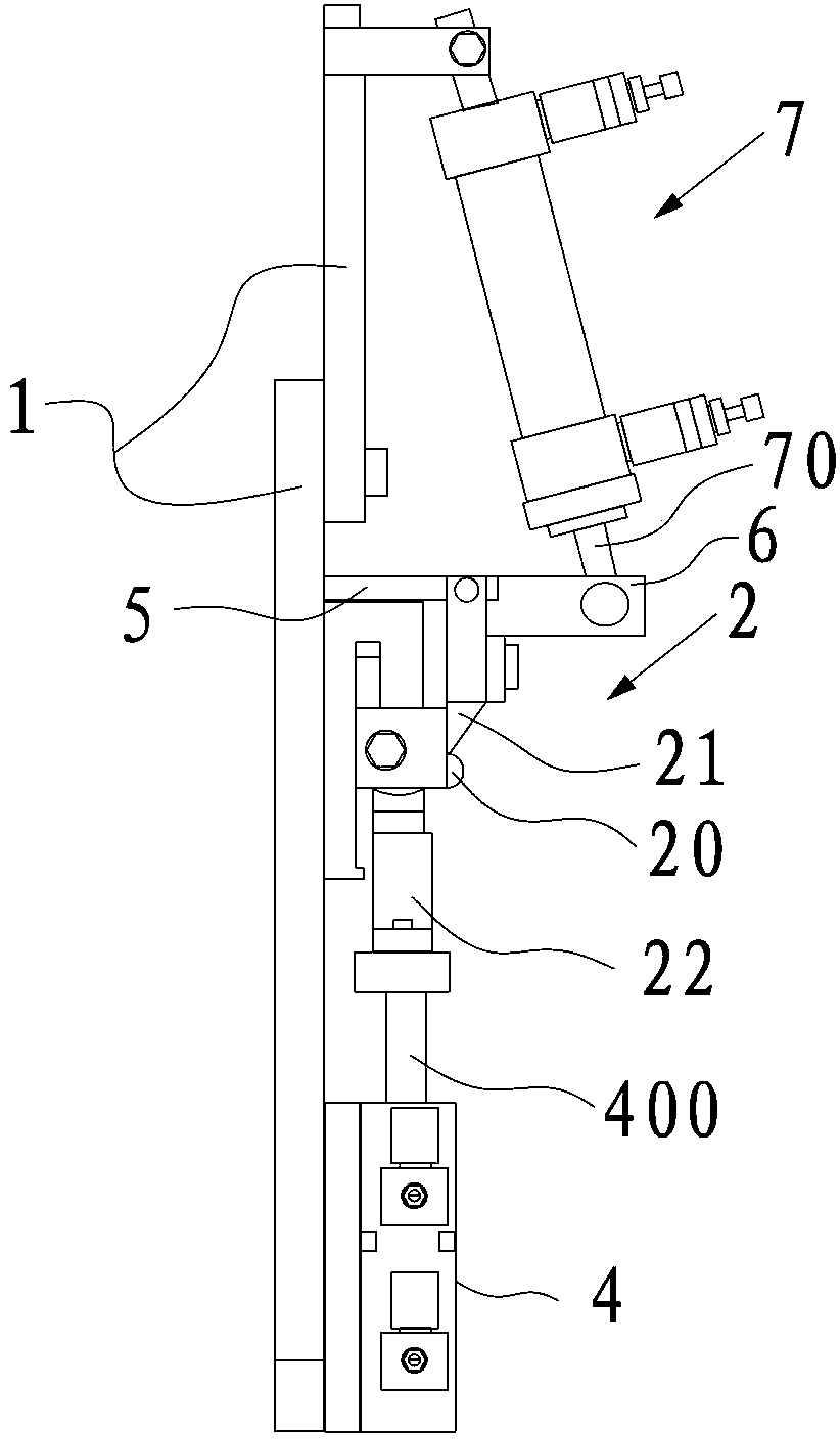
[0019] Such as figure 1 and figure 2 As shown, the profiling fixture provided in this embodiment is specifically used to fix the computer shaft, and its structure includes a base 1 and a positioning module 2 arranged on the base 1. The positioning module 2 has a shaft capable of placing the shaft. The type groove 3 extends along the length direction of the base 1 .

[0020] The above-mentioned positioning module 2 includes a first module 20 fixed on the base 1, and a second module 21 and a third module 22 whose splicing parts form the groove 3, wherein the first module 20 extends along the length direction of the groove 3 and its shape It is the same as the inner hole of the rotating shaft, and the rotating shaft can be inserted on the outer surface of the first module 20, the second module 21 is fixed on the base 1 and can touch the side of the rotating shaft, and the third module 22 can be along the width of the base 1 Move towards the second module 21 to adjust the...


PUM


Abstract

The invention relates to a copying machining fixture, which comprises a base and a positioning module, wherein the positioning module is arranged on the base and is provided with a groove which is used for containing a to-be-processed product, the groove extends in the length direction of the base, the positioning module comprises a first module, a second module and a third module, the first module is fixedly arranged on the base, the splicing parts of the second module and the third module forms the groove, the first module extends in the length direction of the groove, the shape of the first module is the same as the shape of an inner hole of the to-be-processed product, the to-be-processed product is inserted into the outer surface of the first module, the second module is fixedly arranged on the base and is abutted against the side surface of the to-be-processed product, and the third module can move in the width direction of the base to the second module so as to adjust the width of the groove. The to-be-processed product is inserted into the first module, the second module is abutted against one side of the to-be-processed product, and meanwhile, the width of the groove is reduced by adjusting the third module, so the to-be-processed product is fixed, the to-be-processed area of the to-be-processed product is accurately positioned, and the quality and the efficiency of the product are improved.

Description

technical field [0001] The invention relates to a jig, in particular to a profiling jig. Background technique [0002] The profiling processing fixture is mainly to select the corresponding processing fixture according to the shape of the product. For example, in the assembly process of a notebook computer, it is necessary to connect the processing system of the computer with the display system. Therefore, it is necessary to process the shaft, and at the same time Most of the material is aluminum, and ordinary vise fixtures cannot meet the processing requirements of the rotating shaft, which is easy to cause deformation of the rotating shaft. At the same time, it is difficult to accurately locate the position of the surface of the rotating shaft, which may easily lead to the scrapping of the entire rotating shaft. Inconvenience. Contents of the invention [0003] The technical problem to be solved by the present invention is to overcome the deficiencies of the prior art a...

Claims


Application Information

Patent Timeline
IPC IPC(8): B23Q3/08
Inventor 欧阳曼平王文科左熊常深山李林何政杨艳桃郑礼貌
Owner 太仓伟利达铭板科技有限公司
Why Eureka
Try Eureka