
Voltage stabilization device in electronic device, voltage stabilization method of voltage stabilization device, and electronic device

A technology of electronic equipment and a voltage stabilizing device, which is applied in the electronic field, can solve problems such as damage to DC bus components, unfavorable equipment structure, and low frequency of use, and achieve the effects of increasing power density, simplifying structure, and maintaining stable working voltage

Active Publication Date: 2013-10-30
SIEMENS AG
View PDF6 Cites 1 Cited by
  • Summary
  • Abstract
  • Description
  • Claims
  • Application Information

AI Technical Summary

Problems solved by technology

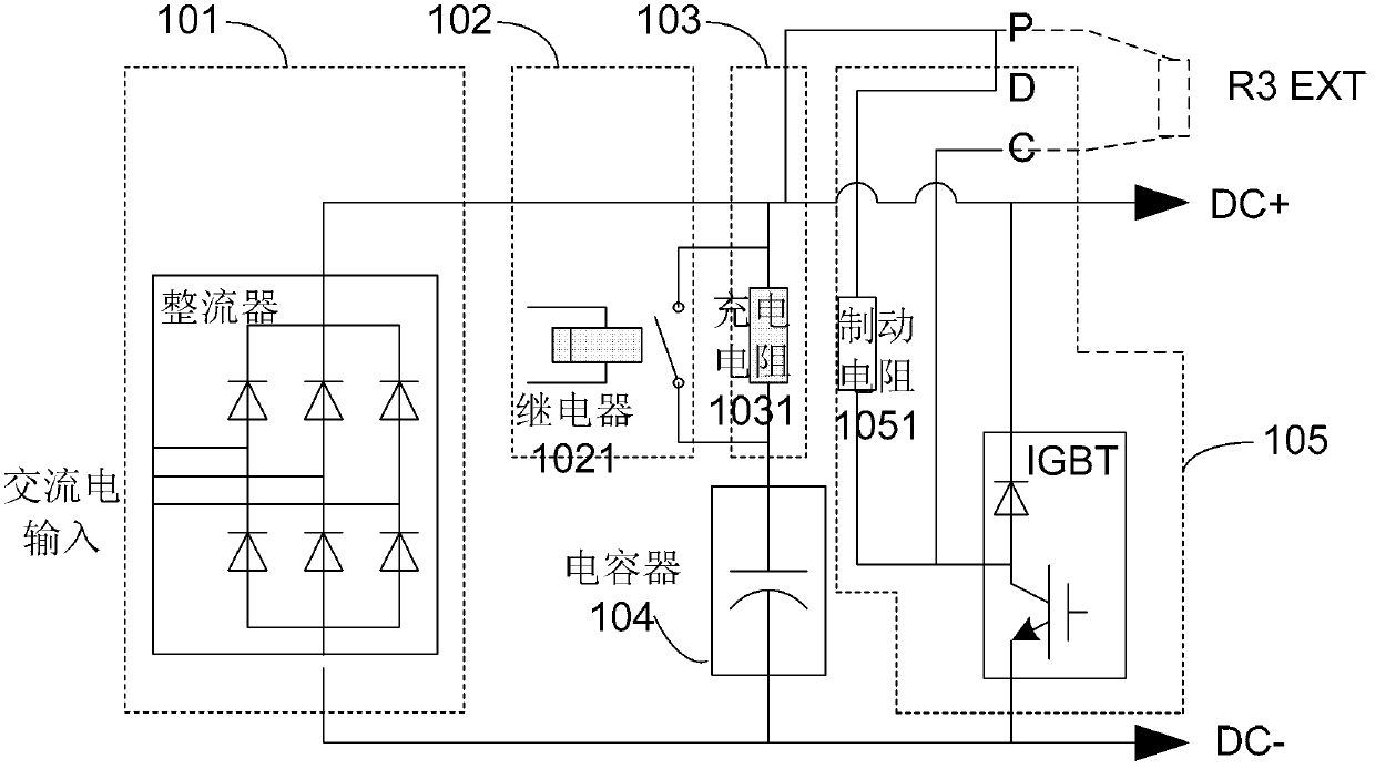
[0003] The surge resistor 1031 in this voltage stabilizing device is essential for limiting the surge current when the electronic equipment is powered on, but usually its size is relatively large, and the frequency of use is not high, and it is only used when the electronic equipment is started. used, so it is very unfavorable for the design of compact equipment structure
[0004] Moreover, when the brake resistor 1051 causes an open circuit (open loop) of the discharge circuit due to a fault, the overvoltage (over voltage) generated on the capacitor 204 will not be released, so the components and parts on the DC bus may be damaged. damage

Method used


Image

  • Voltage stabilization device in electronic device, voltage stabilization method of voltage stabilization device, and electronic device
  • Voltage stabilization device in electronic device, voltage stabilization method of voltage stabilization device, and electronic device
  • Voltage stabilization device in electronic device, voltage stabilization method of voltage stabilization device, and electronic device

Examples


Embodiment Construction

[0026] The present invention will be described in further detail below in conjunction with the accompanying drawings and embodiments. It should be understood that the specific embodiments described here are only used to explain the present invention, and are not intended to limit the protection scope of the present invention.

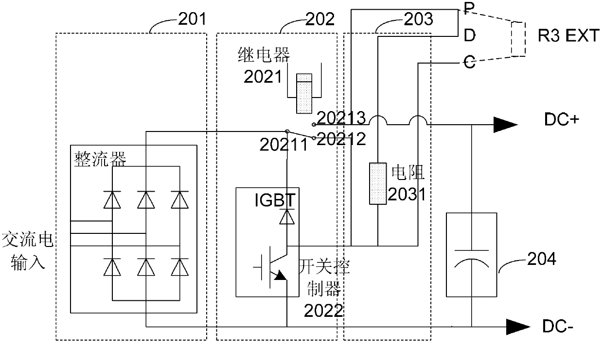
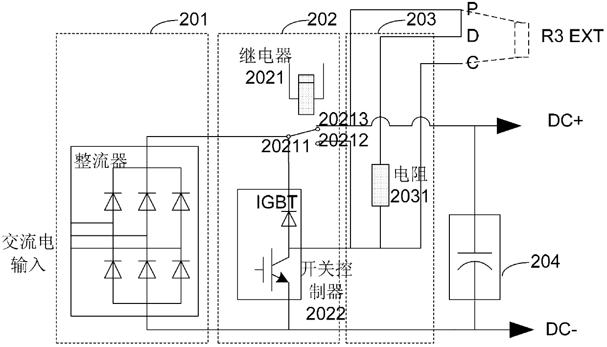
[0027] An embodiment of the present invention proposes a voltage stabilizing device in an electronic device. The voltage stabilizing device includes: a rectifying unit, a charging / discharging mode conversion unit, a charging / discharging unit, and a capacitor; wherein: the rectifying unit is used to convert the input The alternating current is converted into direct current and output to the charging / discharging unit; the charging / discharging mode conversion unit is used to convert the working mode of the charging / discharging unit; the charging / discharging unit includes a resistor, when in the charging mode , charge the capacitor through the resistor; dis...


PUM


Abstract

The embodiment of the invention provides a voltage stabilization device in an electronic device. The voltage stabilization device includes: a rectification unit, a charge / discharge mode conversion unit, a charge / discharge unit, and a capacitor, wherein the rectification unit is used for converting the input alternating current into direct current and outputting the direct current to the charge / discharge unit; the charge / discharge mode conversion unit is used for converting working modes of the charge / discharge unit; the charge / discharge unit includes a resistor, through which the capacitor is charged in a charge mode and is discharged in a discharge mode; and the capacitor is used for stabilizing the working voltage of a direct current bus of the electronic device. The embodiment of the invention also provides a corresponding voltage stabilization method of the voltage stabilization device and an electronic device utilizing the voltage stabilization device. With the voltage stabilization device in electronic device, the voltage stabilization method of the voltage stabilization device, and the electronic device, elements of the direct current bus is prevented from over voltage damage, structure of the electronic equipment is simplified, and thus the power density of the entire power system is improved.

Description

technical field [0001] The invention relates to the field of electronic technology, in particular to a voltage stabilizing device in electronic equipment, a method for realizing voltage stabilizing and an electronic equipment using the voltage stabilizing device. Background technique [0002] At present, voltage stabilizing devices commonly used in electronic equipment in this field such as figure 1 As shown, the voltage stabilizing device at least includes: a rectifying unit 101 ′, a bypass unit 102 , a charging unit 103 , a capacitor (capacitor) 104 and a discharging unit 105 . When the electronic equipment starts, the capacitor 104 is charged through the surge resistor (inrush resistor) 1031 in the charging unit; Relay 1021 bypasses surge resistor 1031 . During the operation of the electronic equipment, the generated energy feedback (energy feedback) will cause the voltage of the capacitor 204 on the DC bus in the above-mentioned electronic equipment to increase. At thi...

Claims


Application Information

Patent Timeline
IPC IPC(8): H02M3/07
Inventor 李浩卓越李鹏程
Owner SIEMENS AG
Learn More