
Electromagnetic component and coil structure thereof

A technology for electromagnetic devices and coils, applied in the field of electromagnetic devices and their coil structures, can solve problems such as difficulty in size and volume

Active Publication Date: 2013-10-30
CYNTEC
View PDF5 Cites 37 Cited by
  • Summary
  • Abstract
  • Description
  • Claims
  • Application Information

AI Technical Summary

Problems solved by technology

However, with the current coil device structure, it is very difficult to further reduce its size and volume.

Method used


Image

  • Electromagnetic component and coil structure thereof
  • Electromagnetic component and coil structure thereof
  • Electromagnetic component and coil structure thereof

Examples


Embodiment Construction

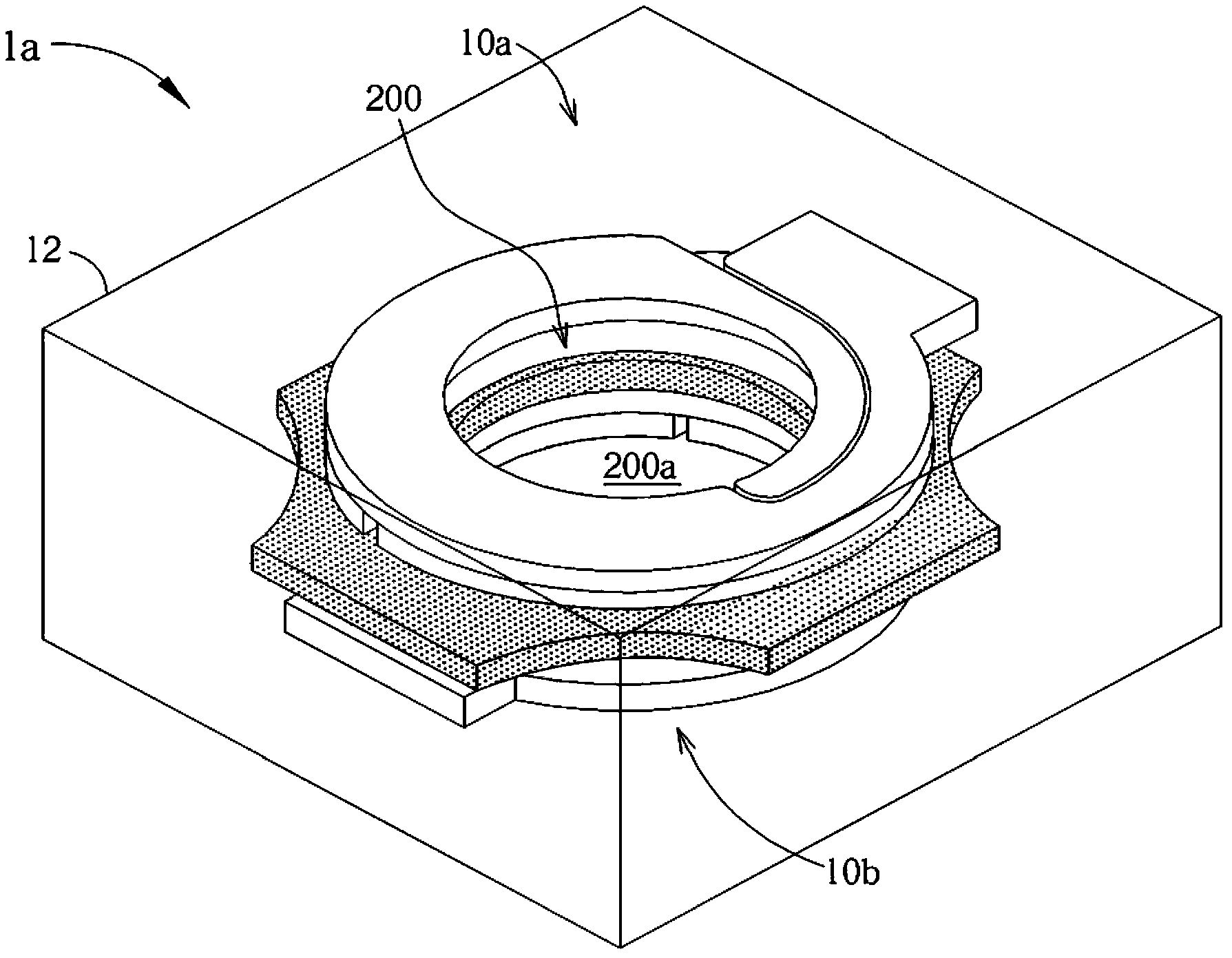
[0051] Hereinafter, the details of the present invention will be described with reference to the accompanying drawings. The content in the accompanying drawings constitutes a part of the detailed description of the specification, and is illustrated in the manner of description of specific examples of feasible embodiments. The following embodiments have described enough details to enable those of ordinary skill in the art to implement it. Of course, other embodiments can also be implemented, or any structural, logical, and electrical changes can be made without departing from the embodiments described in the text. Therefore, the following detailed description should not be regarded as a limitation, on the contrary, the embodiments contained therein will be defined by the appended claims.

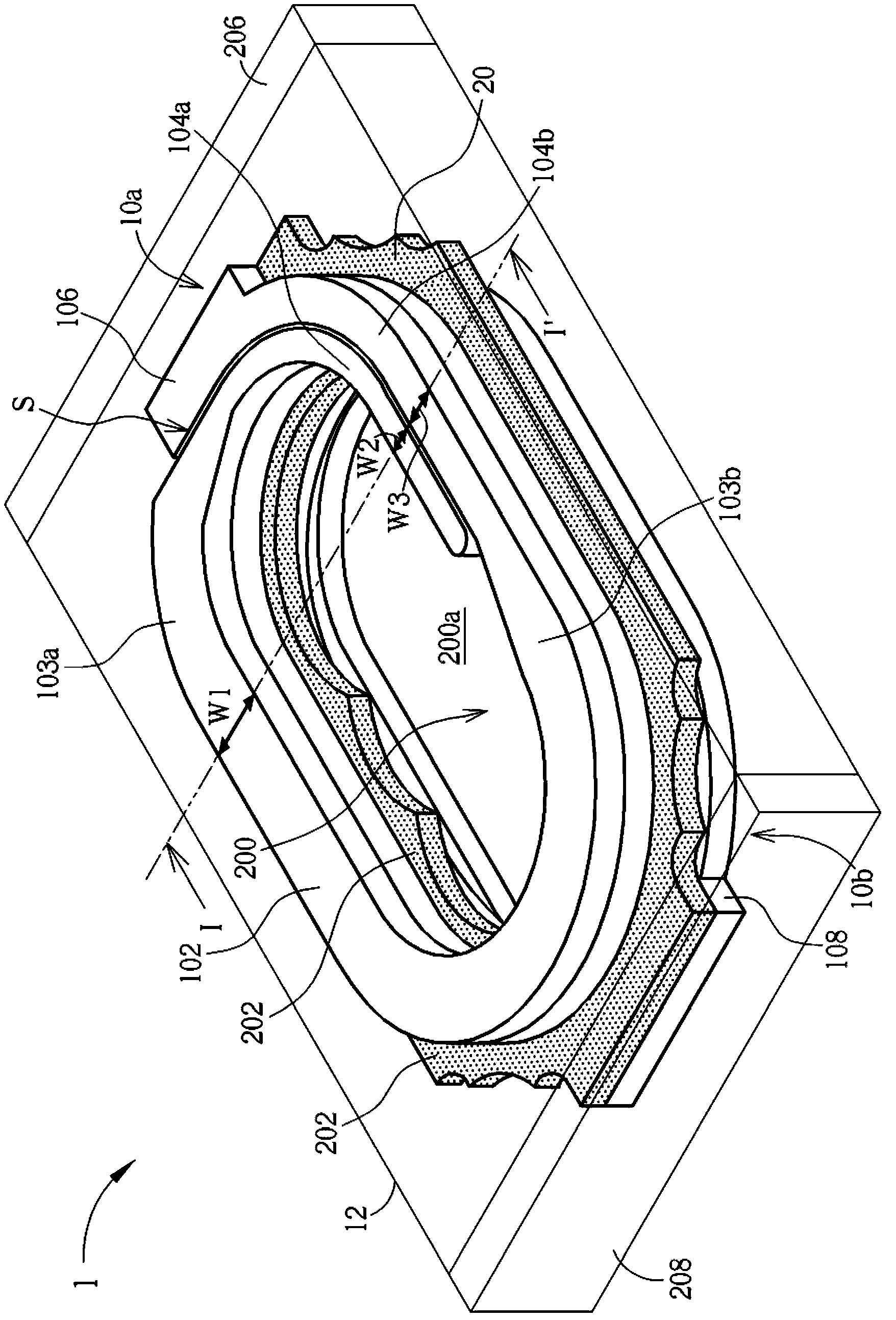
[0052] figure 1 It is a perspective view of a coil structure of an electromagnetic device according to an embodiment of the present invention. Such as figure 1 As shown, the electromagnetic d...


PUM


Abstract

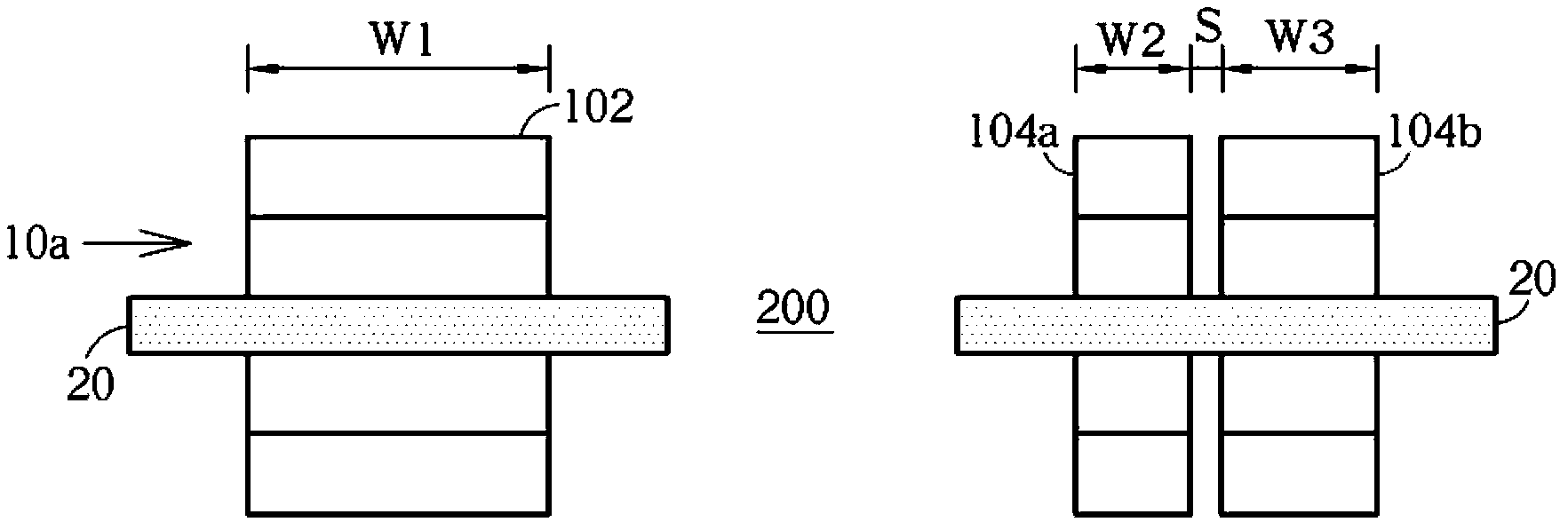
An electromagnetic component including a multi-layer coil structure embedded in a molded body is disclosed. Each layer of the coil structure has a loose middle segment, two slim end segments overlapping each other with a spacing therebetween, and tapered neck segments respectively connecting the loose middle segment with the two slim end segments.

Description

Technical field [0001] The invention relates to an electromagnetic device and its coil structure. Background technique [0002] As those skilled in the art know, in the past, electromagnetic devices such as inductors or choke coils were usually made by winding conductors or wires, such as copper wires coated with insulation, around a cylindrical core. This electromagnetic device is generally designed as a surface mount device (SMD) structure suitable for surface mount technology. [0003] In recent years, with the development of electronic components toward smaller volumes and higher performance, the demand for smaller-sized and high-performance coil devices has increased. In addition, the efficiency of the above-mentioned coil device can be determined from its saturation current (I sat ) And DC resistance (DC resistance, DCR). However, with the current coil device structure, it is very difficult to further reduce its size and volume. [0004] Therefore, there is still a need for ...

Claims


Application Information

Patent Timeline
IPC IPC(8): H01F27/28H01F27/30H01F17/06
Inventor 张炜谦吴嘉琪江朗一吴宗展叶日旭
Owner CYNTEC
Learn More