Eureka AIR delivers breakthrough ideas for toughest innovation challenges, trusted by R&D personnel around the world.

Evaporator

A technology for evaporators and shells, applied to evaporators/condensers, refrigeration components, refrigerators, etc., can solve problems such as air condensation, achieve the effect of improving consistency and solving condensation problems

Active Publication Date: 2015-12-09
GREE ELECTRIC APPLIANCES INC
View PDF8 Cites 0 Cited by
  • Summary
  • Abstract
  • Description
  • Claims
  • Application Information

AI Technical Summary

Problems solved by technology

[0009] The purpose of the present invention is to provide an evaporator to solve the technical problem that the air inside the existing evaporator is prone to condensation

Method used

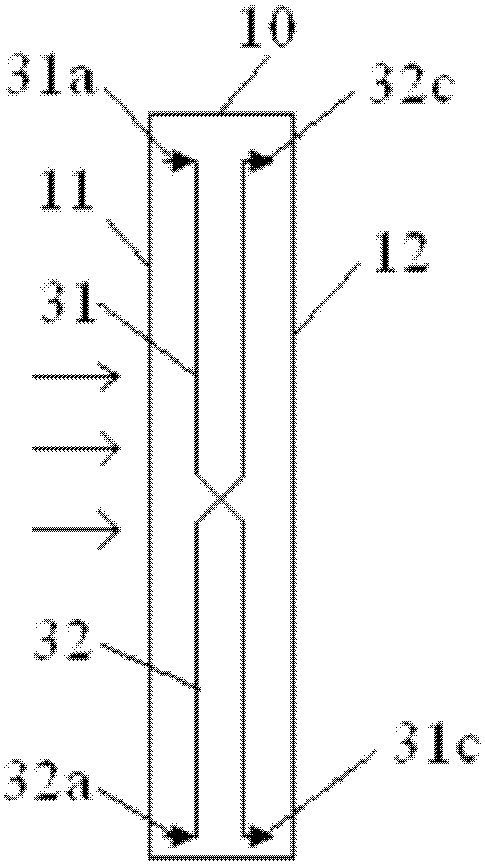
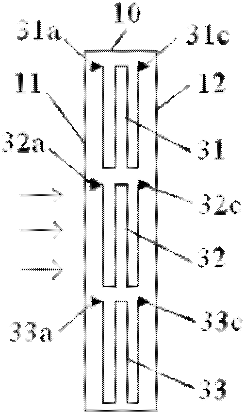

Image

  • Evaporator
  • Evaporator
  • Evaporator

Examples


Embodiment Construction

[0030] The embodiments of the present invention will be described in detail below with reference to the accompanying drawings, but the present invention can be implemented in many different ways defined and covered by the claims.

[0031] Such as Figure 2 to Figure 4 As shown, the present invention provides an evaporator, which includes: a housing 10; a plurality of refrigerant pipelines arranged in the housing 10, each refrigerant pipeline has a refrigerant inlet and a refrigerant outlet, wherein any A refrigerant inlet and any refrigerant outlet are arranged in pairs along the height direction of the housing 10 , the height direction is perpendicular to the flow direction of air blowing through the housing 10 , and any pair of refrigerant inlets and refrigerant outlets are located at the same height.

[0032] Arranging any refrigerant inlet and refrigerant outlet in pairs at the same height in the housing 10 can improve the consistency of temperature perpendicular to the di...


PUM


Abstract

The invention provides an evaporator. The evaporator comprises a shell, and multiple refrigerant pipelines arranged in the shell, wherein each refrigerant pipeline is provided with a refrigerant inlet and a refrigerant outlet; refrigerant inlet and any refrigerant outlet are arranged along the height direction of the shell in a pair manner; the height direction is vertical to the flowing direction of the air passing through the shell; any refrigerant inlet and any refrigerant outlet in pair are located at the same height. As any refrigerant inlet and any refrigerant outlet of the multiple refrigerant pipelines are arranged at the same height in the shell in the pair manner, the evaporator provided by the invention can improve consistence of temperature in the direction vertical to the air flowing direction, ensures consistent treatment effects for hot and wet air by each pair of the refrigerant inlet and the refrigerant outlet, ensures the internal temperature field of the shell to be in a reasonable range, and solves the condensation problem caused by uneven temperature fields.

Description

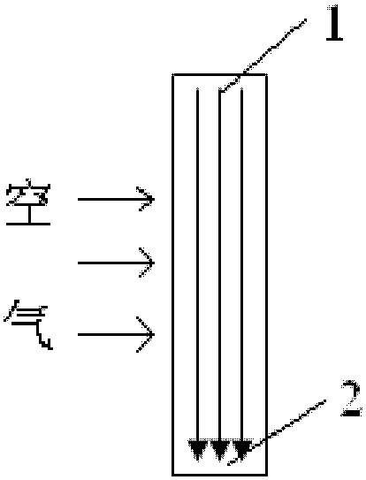
technical field [0001] The present invention relates to the technical field of air conditioning, in particular to an evaporator. Background technique [0002] If the indoor unit of the air conditioner produces too much condensed water, it will not only reduce the safety and stability of the refrigeration system, but once the condensed water is blown into the room, it will reduce the air quality in the room and affect the comfort. [0003] Such as figure 1 As shown in the figure, in the traditional multi-channel evaporator, the refrigerant of each channel enters from the first end 1 of the evaporator and exits from the second end 2, and the air blows through the evaporator along the direction perpendicular to the flow direction of the refrigerant. . Due to the large temperature difference between the refrigerant inlet and the refrigerant outlet of the evaporator, the temperature difference of the air flowing through the first end 1 and the second end 2 of the evaporator is ...

Claims


Application Information

Patent Timeline
Patent Type & Authority Patents(China)
IPC IPC(8): F25B39/02
Inventor 陈华康陈钦文周子敬
Owner GREE ELECTRIC APPLIANCES INC
Why Eureka
Eureka Blog
Learn More