
Low-temperature welding double-eccentric aluminum butterfly valve

A low-temperature welding, double eccentric technology, applied in the direction of lift valve, valve details, valve device, etc., can solve the problems of leakage, leakage at the joint between pipeline and valve, different material shrinkage rate, etc., to improve the flow capacity and reduce the rotation start. The effect of closing torque and improving service life

Inactive Publication Date: 2013-10-30
维士威(上海)控制阀门有限公司
View PDF4 Cites 1 Cited by
  • Summary
  • Abstract
  • Description
  • Claims
  • Application Information

AI Technical Summary

Problems solved by technology

Since it only adopts this connection method, it will inevitably cause leakage at the connection between the pipe and the valve.
Because the installation of this project is carried out at room temperature, although the clamping nut is tightened tightly, the pressure test does not leak, but when the actual low temperature working condition (-196°C), due to the shrinkage of the material of the valve body and the transition piece Different rates create gaps, resulting in leaks
Once this phenomenon occurs, it cannot be solved for a while, because the low-temperature butterfly valve is installed in the air separation tower filled with heat-insulating materials. First, the operation of the entire air separation plant (including all supporting units) must be stopped, and then the tower must be cleaned. Repairs can only be carried out after the internal heat insulation material is installed, so this matter has not been fundamentally resolved, and the problem of worrying about the future will always exist

Method used


Image

  • Low-temperature welding double-eccentric aluminum butterfly valve
  • Low-temperature welding double-eccentric aluminum butterfly valve
  • Low-temperature welding double-eccentric aluminum butterfly valve

Examples


Embodiment Construction

[0036] The present invention will be further described below in combination with principle diagrams and specific operation examples.

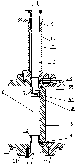
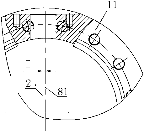
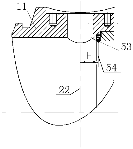
[0037] Such as figure 1 As shown in , a low-temperature welded double eccentric aluminum butterfly valve includes a valve body 1, a valve stem 2, a valve disc 5 and a pipe hole 8. The pipe hole 8 is a cavity formed between the valve body 1 and the valve disc 5.

[0038] In one example of the present invention, the valve body 1 is composed of a left valve body 11 and a right valve body 12, the right valve body 12 is placed in the left valve body 11, and the right valve body 12 is inserted into the left valve body by hexagon socket screws 11, the valve body 1 is a valve body with a welded structure, and the welding groove of the valve body 1 is consistent with the welding groove of the pipeline, so that the valve body 1 can be directly welded to the pipeline, and can also be welded on the welded groove There is a groove (not marked in the figure...


PUM


Abstract

The invention discloses a low-temperature welding double-eccentric aluminum butterfly valve which comprises a valve body, a valve rod, a valve flap and a pipeline hole. The pipeline hole is a cavity formed between the valve body and the valve flap. The valve body comprises a left valve body and a right valve body which are fixedly integrated. The valve rod is disposed in a shaft hole of the left valve body. A first central axis of the valve rod deviates the central line of the pipeline hole to form a first eccentric structure. A valve seat is disposed between the left valve body and the right valve body. The valve flap is hermitically connected with the valve seat, and the contact face of the valve seat and the valve flap is a seal face. One end of the valve flap is fixed at the bottom end of the valve rod, and the other end thereof is located on a cylinder of the left valve body. The center of the seal face deviates a second central axis of the valve rod to form a second eccentric structure. By welding and the double-eccentric structure, opening torque of the valve flap can be reduced, abrasion can be lowered, and service life of the valve seat can be prolonged.

Description

technical field [0001] The invention relates to a butterfly valve device, in particular to a low-temperature welded double-eccentric aluminum butterfly valve. Background technique [0002] Butterfly valve refers to a valve whose closing part (disc) is a disc, which rotates around the valve shaft to achieve opening and closing. It mainly plays the role of cutting and throttling on the pipeline. [0003] At present, there are two types of low-temperature butterfly valves suitable for cryogenic working conditions; one type can be directly welded to aluminum alloy pipes, and the other type is to connect aluminum alloy pipes with wafer-type valves through "transition pieces". Cryogenic stainless steel butterfly valve connection. [0004] Pneumatic low-temperature aluminum butterfly valve; it is a single eccentric butterfly valve, because the single eccentric butterfly valve uses the same PTFE material as the seal on the valve body and disc, which indeed solves the problem of con...

Claims


Application Information

Patent Timeline
IPC IPC(8): F16K1/22F16K1/48F16K41/02F16K1/42F16K1/36F16K27/02F16K27/10
Inventor 盛波
Owner 维士威(上海)控制阀门有限公司
Learn More