
Turboprop engine and usage method thereof

A turboprop and engine technology, applied in the direction of machines/engines, jet propulsion devices, etc., can solve the problems of short working time, unfavorable power-to-weight ratio, and high consumption of liquid oxygen and kerosene

Inactive Publication Date: 2013-10-30
李吉光
View PDF0 Cites 7 Cited by
  • Summary
  • Abstract
  • Description
  • Claims
  • Application Information

AI Technical Summary

Problems solved by technology

[0002] The current turboprop engines, such as turboprop 5, turboprop 6, and turboprop 9, all work by simply taking in air from the air. To increase the power, at present, it is mainly to increase the number of stages of the compressor and increase the temperature of the gas in front of the turbine. The former is unfavorable for improving the power-to-weight ratio. The latter must use high-temperature-resistant, high-performance turbine blade materials, coating materials and advanced cooling technology. It is very difficult to increase the gas temperature before the turbine. The essence of increasing the number of compressor stages is Increase the pressure of the compressed air after the compressor is compressed, but increase the intake pressure to achieve the same purpose. The turbocharged diesel engine increases the intake pressure through turbocharging, thereby increasing the power, but the turboprop engine cannot be used. Turbocharging is used to increase the intake pressure. Although the thrust-to-weight ratio of the turbo / rocket engine is high, only liquid oxygen and kerosene are burned in the main combustion chamber, without compressed air. The compressor provides compressed air for the afterburner. This engine is not designed to increase the thrust-to-weight ratio of the main combustion chamber that burns compressed air, and the consumption of liquid oxygen and kerosene is high, and the working time is too short. Therefore, the turbo / rocket engine cannot be used to increase the power of the turboprop engine , improving the power-to-weight ratio

Method used


Image

  • Turboprop engine and usage method thereof
  • Turboprop engine and usage method thereof

Examples


Embodiment Construction

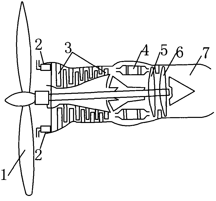
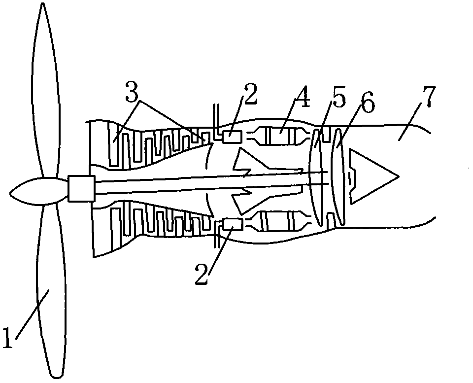
[0017] Refer to attached figure 1 , 2 A turboprop engine according to the present invention includes a propeller 1, a pressure regulating nozzle 2, an axial flow compressor 3, a combustion chamber 4, a high-pressure turbine 5, a low-pressure turbine 6, an exhaust nozzle 7, etc., that is, the current turboprop All structures of the engine and the pressure regulating nozzle 2, wherein the pressure regulating nozzle 2 can be at the engine air intake, such as figure 1 As shown, it can also be between the axial flow compressor 3 and the combustion chamber 4, such as figure 2 As shown, the pressure regulating nozzle 2 does not hinder the air intake of the engine, and there is a fuel nozzle in the combustion chamber 4, which is omitted from drawing, and the low-pressure turbine 6 is connected with the propeller 1.

[0018] When the turboprop engine is the present invention figure 1 , 2 During the shown turboprop engine, after starting, the high-pressure air or liquid oxygen that...


PUM


Abstract

The invention discloses a turboprop engine and a usage method thereof. The turboprop engine comprises a propeller, an axial-flow compressor, a combustion chamber, high-pressure and low-pressure turbines and an exhaust nozzle and is characterized by also comprising a pressure-regulating nozzle. The method comprises that high-pressure air or liquid oxygen which is higher than and capable of increasing the air inlet pressure or the compressed air pressure inside the combustion chamber is ejected into an air inlet or the combustion chamber of the engine through the pressure-regulating nozzle after the engine is started, the high-pressure air or the liquid oxygen is compressed by the axial-flow compressor or is burnt directly in the combustion chamber to work, on the premise that the front gas temperature of the high-pressure turbine is not increased, the power of the engine is increased, after the power is increased and the intake air of the engine from the air satisfies the increased power requirement, ejection of the pressure-regulating nozzle is stopped, only the intake air from the air is used, then the fuel-injection quantity of a fuel nozzle inside the combustion chamber is controlled to keep the power unchanged or increase the power, the power-weight ratio of the engine is higher than that of the engine without ejection of the pressure-regulating nozzle, stages of the axial-flow compressor are not increased, and the front gas temperature of the high-pressure turbine is not increased.

Description

technical field [0001] The invention relates to a turboprop engine and a method for using the same, belonging to the technical field of turboprops, especially military turboprop engines. Background technique [0002] The current turboprop engines, such as turboprop 5, turboprop 6, and turboprop 9, all work by simply taking in air from the air. To increase the power, at present, it is mainly to increase the number of stages of the compressor and increase the temperature of the gas in front of the turbine. The former is unfavorable for improving the power-to-weight ratio. The latter must use high-temperature-resistant, high-performance turbine blade materials, coating materials and advanced cooling technology. It is very difficult to increase the gas temperature before the turbine. The essence of increasing the number of compressor stages is Increase the pressure of the compressed air after the compressor is compressed, but increase the intake pressure to achieve the same purp...

Claims


Application Information

Patent Timeline
Patent Type & Authority Applications(China)
IPC IPC(8): F02K3/00F02K1/00F02K1/54
Inventor 李吉光
Owner 李吉光
Learn More