Turnover machine

A technology of turning machine and frame, which is applied in the field of turning machines, which can solve the problems of long installation period, high ground requirements, and many power equipment, and achieve the effect of reducing the working height

Inactive Publication Date: 2015-12-16
张铭勇
View PDF4 Cites 1 Cited by
  • Summary
  • Abstract
  • Description
  • Claims
  • Application Information

AI Technical Summary

Problems solved by technology

However, this kind of turning machine has the following disadvantages: the movement track of the fork bar is a full circle, which makes the working height of the whole turning machine high, but on the production line, the working height of the pressing plate cannot be on the same height, and some need a Due to the high level difference of the blanking, it is necessary to dig a sinkhole on the ground, resulting in: 1) large basic investment; 2) long installation period; 3) for enterprises undergoing technological transformation, normal production will be affected; 4) sinking The pit is not easy to clean the site, and has high requirements on the ground; 5) There are many power equipment, large investment in equipment, and high energy consumption

Method used


Image

  • Turnover machine
  • Turnover machine
  • Turnover machine

Examples


Embodiment Construction

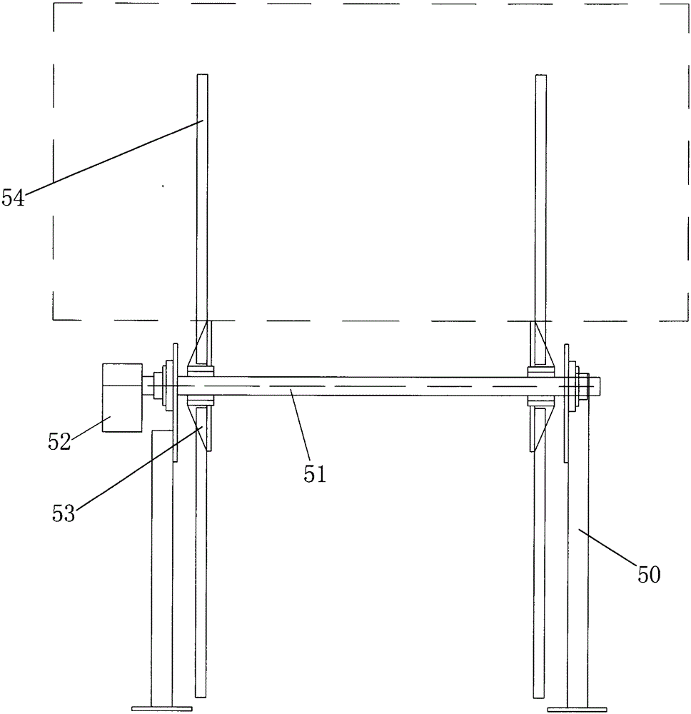
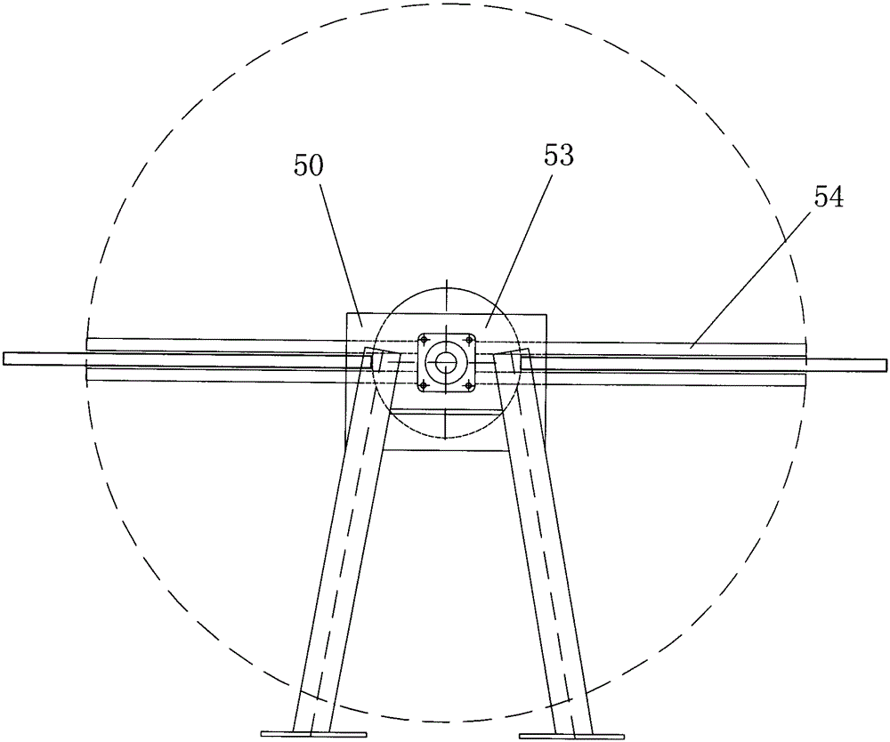
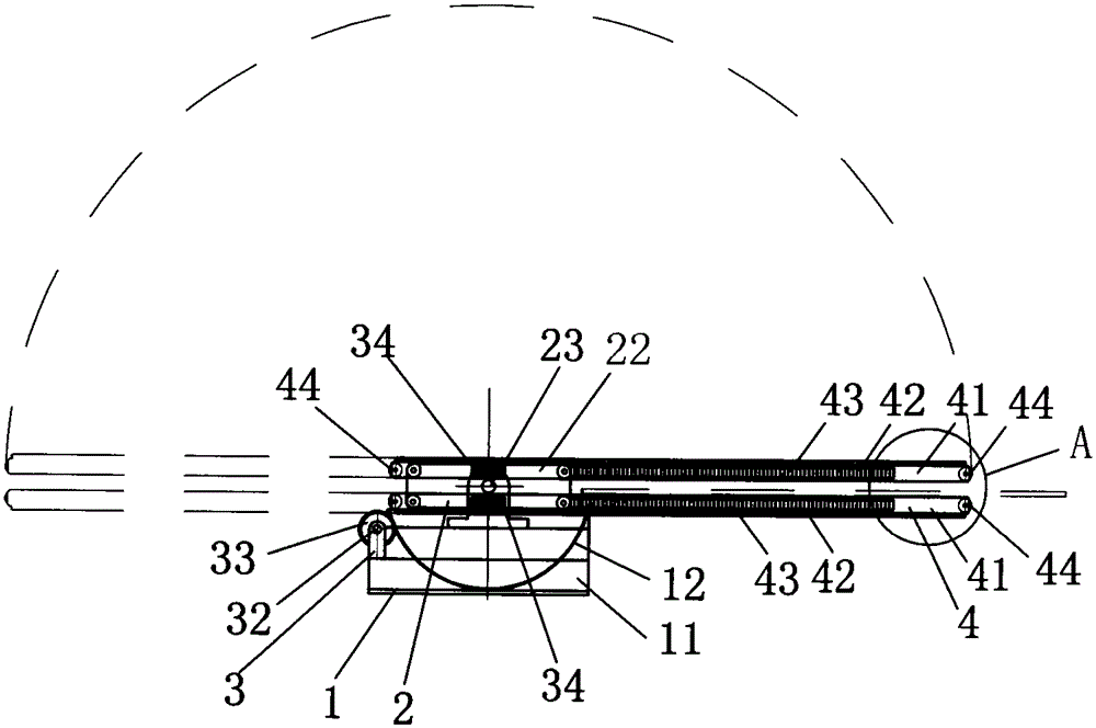
[0020] Such as Figure 3 to Figure 7 Shown, the turnover machine of low working height of the present invention, this turnover machine comprises frame 1, rotating mechanism 2, moving mechanism 3 and at least four sets of fork bars 4, and turning mechanism 2 and moving mechanism 3 are all horizontally installed on the machine. On the frame 1, when the plate held by the two-fork lever 4 from the plate-feeding position, after the rotating mechanism 2 rotates 180°, the two-fork lever 4 is driven by the moving mechanism 3, and is pushed back to the original plate-feeding position, reaching the two-fork, 4. The purpose of circularly clamping the sheet material and turning over, because the fork bar 4 only rotates in the upper half of the turning machine, reduces the working height of the turning machine.

[0021] The rotating mechanism 2 of the described turning machine comprises a rotating drive device 21, at least two rotating disks 22, a rotating shaft 23 and a plurality of group...


PUM


Abstract

The invention discloses a turning-over machine which comprises a machine frame, a rotating mechanism, a moving mechanism and at least four sets of fork rods. The rotating mechanism and the moving mechanism are both installed on the machine frame. The rotating mechanism is provided with at least two rotating discs fixed at two ends of a rotating shaft. Each rotating disc is provided with a moving roller supporting and limiting the fork rods to conduct linear movement. Two pairs of fork rods are symmetrically and vertically installed on the moving rollers with the axis of the rotating shaft as the symmetrical center. Two pairs of synchronous gears are connected coaxially, meshed with synchronous racks on the outer sides of the two pairs of fork rods and vertically installed on the rotating shaft. When a moving gear of the moving mechanism rotates, the moving gear drives moving racks on the lower sides of the lower fork rods to move linearly. Under the effect of the synchronous gears and the synchronous racks, moving racks on the upper fork rods also move in the same direction synchronously. When the two pairs of fork rods clamp a plate from the plate feeding position, after the rotating mechanism rotates through 180 degrees, the two pairs of fork rods are driven by the moving mechanism to be pushed backwards to the original plate feeding position to achieve the aim that the two pairs of fork rods clamp the plate in a circulation mode and turn over the plate. Due to the fact that the fork rods only rotate on the upper half ring of the turning-over machine, working height of the turning-over machine is reduced.

Description

technical field [0001] The invention relates to the field of sheet material manufacturing, in particular to a turning machine applied to a sheet material production line. Background technique [0002] Such as figure 1 and figure 2 As shown, the existing turning machine includes a frame 50, a drive shaft 51, a motor 52, a rotating disk 53 and a fork bar 54. The drive shaft 51 is installed horizontally on the frame 50 and is driven by a motor 52. There are two rotating disks 53, which are installed vertically on both ends of the driving shaft 51 respectively. Fork rods 54 are installed on the two rotating disks 53. When the motor 52 works, it drives the fork bar 54 fixed on the rotating disk 53 to rotate through the drive shaft 51, that is, the movement track of the fork bar 54 is a complete circle. However, this kind of turning machine has the following disadvantages: the movement track of the fork bar is a full circle, which makes the working height of the whole turning ...

Claims


Application Information

Patent Timeline
Patent Type & Authority Patents(China)
IPC IPC(8): B65H15/00
Inventor 张铭勇
Owner 张铭勇
Why Eureka
Try Eureka