Motor drive apparatus
A motor drive and motor technology, applied in the field of motor drive devices, can solve the problems of insufficient heat radiation performance of heat sinks and the like
- Summary
- Abstract
- Description
- Claims
- Application Information
AI Technical Summary
Problems solved by technology
Method used
Image


Examples
no. 1 approach
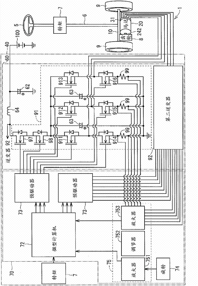
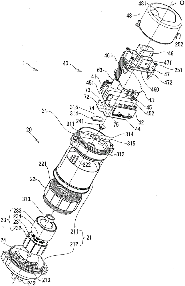
[0017] Referring to the first embodiment shown Figure 1 to Figure 5 , the motor drive device 1 is used in an electric power steering system (EPS). The motor drive device 1 is used in EPS of a vehicle and includes a motor 20 , an end frame 31 and an electronic control unit 40 . By arranging the shaft 24 parallel to the axis of the rack 10, the motor drive 1 is attached relative to the rack 10 connecting the left and right wheels 9 of the vehicle. When the driver operates the steering wheel 5 , the torque generated in the steering shaft 6 by the steering operation is detected by the torque sensor 7 . The motor drive device 1 generates torque for assisting a steering operation based on a signal output from a torque sensor 7 and a vehicle speed signal transmitted from a CAN (Controller Area Network) or the like. This torque is transmitted from the output end 242 of the shaft 24 of the motor 20 to the rack 10 through the gear 8 to the rack 10 .
[0018] Electronic control unit ...
no. 2 approach
[0058] According to the second embodiment, the motor drive device such as Image 6 Constructed as shown.
[0059] Specifically, the end frame 32 has concavo-convex portions 321 formed on radially outer wall surfaces (outer wall surfaces) of the side walls of the end frame 32 . The concavo-convex portion 321 includes a convex portion 322 and a concave portion 323 . The protrusion 322 protrudes on the side wall in a radially outward direction and extends longitudinally, ie in the direction of the axis of rotation O. As shown in FIG. The concave portion 323 is recessed on the convex portion 322 in a radially inward direction and extends in the direction of the rotation axis O. As shown in FIG. The convex portions 322 and the concave portions 323 are alternately arranged in the circumferential direction.
[0060] Since the concavo-convex portion 321 is formed on the radially outer wall surface of the side wall of the end frame 32 , the surface area of the outer wall surface o...
no. 3 approach
[0062] According to the third embodiment, the motor drive device such as Figure 7 Constructed as shown.
[0063] Specifically, the end frame 33 has a concavo-convex portion 331 formed on the radially outer wall surface of the side wall of the end frame 33 . The concavo-convex portion 331 includes a convex portion 332 and a concave portion 333 . The protrusion 332 protrudes on the side wall in the radially outward direction and extends in the circumferential direction. The recess 333 is recessed on the side wall in the radially inward direction and extends in the circumferential direction. The protrusions 332 and the recesses 333 are arranged alternately in the direction of the axis of rotation O. As shown in FIG.
[0064] Since the concavo-convex portion 331 is formed on the radially outer wall surface of the side wall of the end frame 33 , the surface area of the outer wall surface of the side wall of the end frame 33 is increased. Therefore, the heat radiation perform...
PUM
 Abstract
Description
Claims
Application Information
 - R&D
- Intellectual Property
- Life Sciences
- Materials
- Tech Scout
- Unparalleled Data Quality
- Higher Quality Content
- 60% Fewer Hallucinations
Browse by: Latest US Patents, China's latest patents, Technical Efficacy Thesaurus, Application Domain, Technology Topic, Popular Technical Reports.
© 2025 PatSnap. All rights reserved.Legal|Privacy policy|Modern Slavery Act Transparency Statement|Sitemap|About US| Contact US: help@patsnap.com