
Current limiting charging circuit

A technology of current-limiting charging and current-limiting resistors, which is applied to battery circuit devices, circuit devices, collectors, etc., can solve the problems of insufficient over-current protection function and easy damage to charging circuits, etc., to reduce current and prolong service life , the effect of preventing burning

Inactive Publication Date: 2013-10-23
OCEANS KING LIGHTING SCI&TECH CO LTD +1
View PDF2 Cites 6 Cited by
  • Summary
  • Abstract
  • Description
  • Claims
  • Application Information

AI Technical Summary

Problems solved by technology

[0002] Because the traditional charger does not have a perfect over-current protection function during charging, when the circuit is abnormal and the current is too large, it is easy to damage the charging circuit

Method used


Image

  • Current limiting charging circuit
  • Current limiting charging circuit
  • Current limiting charging circuit

Examples


Embodiment Construction

[0020] The following will clearly and completely describe the technical solutions in the embodiments of the present invention with reference to the accompanying drawings in the embodiments of the present invention. Obviously, the described embodiments are only some, not all, embodiments of the present invention. Based on the embodiments of the present invention, all other embodiments obtained by persons of ordinary skill in the art without creative efforts fall within the protection scope of the present invention.

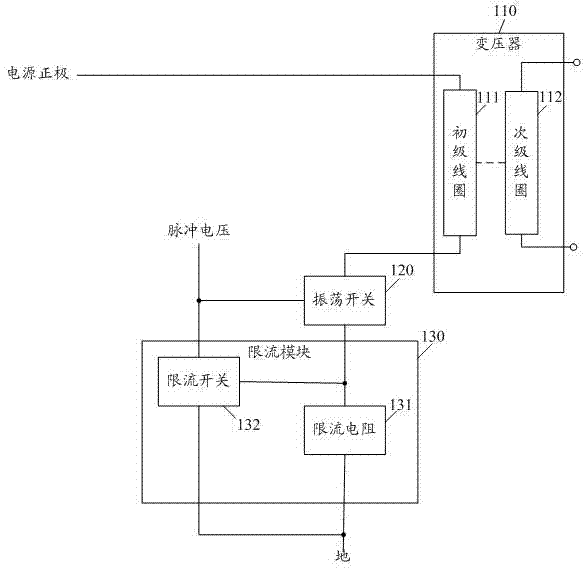
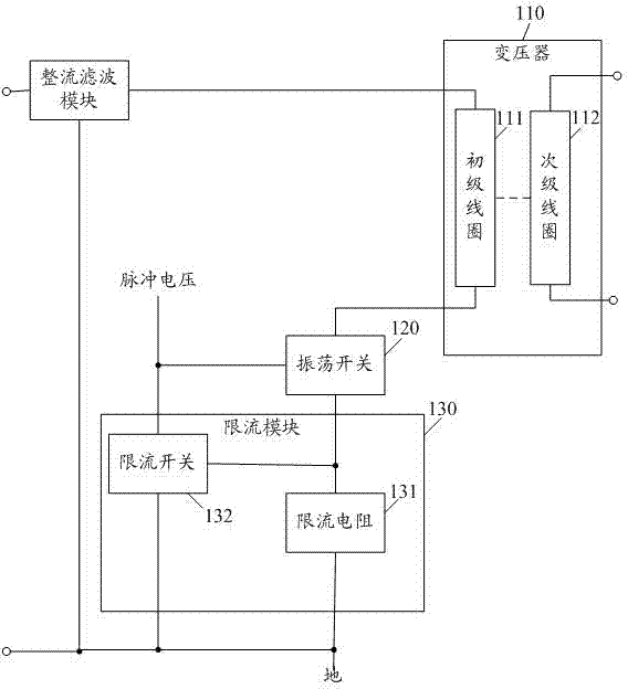
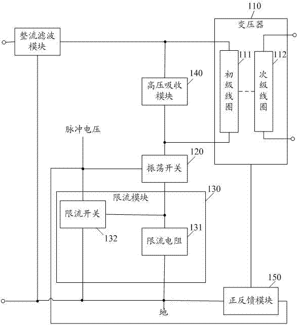
[0021] See figure 1 , is a schematic structural diagram of a preferred embodiment of the current-limiting charging circuit provided by the present invention. The current-limiting charging circuit includes a transformer 110 , an oscillation switch 120 and a current-limiting module 130 , the current-limiting module 130 includes a current-limiting resistor 131 and a current-limiting switch 132 , and the transformer 110 includes a primary coil 111 and a secondary coil ...


PUM


Abstract

The embodiment of the invention discloses a current limiting charging circuit comprising a transformer, an oscillation switch and a current limiting module. The current limiting module comprises a current limiting resistor and a current limiting switch. A primary coil of the transformer, the oscillation switch and the current limiting resistor are in series connection in order and then are connected between an anode of a power supply and the ground. A control end of the oscillation switch is communicated with pulse voltage. The current limiting switch is connected between the control end of the oscillation switch and the ground. A control end of the current limiting switch is connected with a common node of the current limiting resistor and the oscillation switch. By employing the current limiting charging circuit, the current of the charging circuit can be effectively limited, the burning of a component due to overcurrent is prevented, and the service life of the charging circuit is prolonged.

Description

technical field [0001] The invention relates to a battery charging circuit, in particular to a current-limiting charging circuit. Background technique [0002] Because the traditional charger does not have a perfect over-current protection function during charging, when the circuit is abnormal and the current is too large, it is easy to damage the charging circuit. Contents of the invention [0003] The technical problem to be solved by the embodiments of the present invention is to provide a current-limited charging circuit. It can limit the current of the charging circuit and prolong the service life of the charger. [0004] In order to solve the above technical problems, an embodiment of the present invention provides a current-limiting charging circuit, including a transformer, an oscillation switch, and a current-limiting module. The current-limiting module includes a current-limiting resistor and a current-limiting switch. The primary coil of the transformer, The o...

Claims


Application Information

Patent Timeline
Patent Type & Authority Applications(China)
IPC IPC(8): H02J7/04
Inventor 周明杰管伟芳
Owner OCEANS KING LIGHTING SCI&TECH CO LTD
Learn More