Minitype piezoelectric diaphragm pump
A micro-diaphragm pump and piezoelectric technology, applied in the fields of flow control and actuators, can solve the problems of adhesion and separation of diaphragm and piezoelectric bimorph, separation failure of piezoelectric bimorph and diaphragm, etc., to simplify installation and electrical connection , The flow design is controllable and the reliability is high.
- Summary
- Abstract
- Description
- Claims
- Application Information
AI Technical Summary
Problems solved by technology
Method used
Image

Examples
Embodiment 1
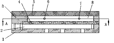
[0045] Embodiment 1 is a single-cavity piezoelectric micro-diaphragm pump composed of a single piezoelectric vibrator, such as Figure 1-15 shown. The piezoelectric miniature diaphragm pump is composed of base plate 1, piezoelectric vibrator 2, frame body 3, diaphragm 4, cover plate 5, discharge valve 6, and inlet valve 7 ( figure 1 , figure 2 ). The piezoelectric vibrator 2 is installed in the installation cavity formed by the bottom plate 1 and the frame body 3 , and the diaphragm 4 is placed on the upper part of the cantilever vibration part of the piezoelectric vibrator, forming a cavity 8 with the frame 3 and the cover plate 5 . The deformation of the diaphragm 3 is driven by the arched bending or warping deformation of the piezoelectric vibrator 2, which in turn causes the volume change of the pump cavity 8 to complete the process of entering and discharging the fluid.
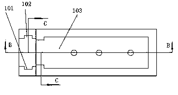
[0046] The bottom plate 1 is formed of a resin material, and a rectangular recess 103 of the can...
Embodiment 2
[0056] This embodiment is a single-cavity piezoelectric diaphragm pump with multiple piezoelectric vibrators arranged side by side, and three piezoelectric vibrators are arranged side by side (referred to as 3×1×1 arrangement, the same below) as an example for illustration. Taking the piezoelectric vibrator in Embodiment 1 as the basic driving unit, and arranging multiple piezoelectric vibrators side by side, the volume of the cavity can be enlarged, the deformation of the cavity can be increased, and the delivery volume of the fluid can be increased. Compared with Example 1, the dimensions of the bottom plate, frame, diaphragm, and cover plate along the length direction of the piezoelectric vibrator remain unchanged, while the dimensions in the width direction increase according to the arrangement; the installation of the three piezoelectric vibrators leads to the installation and positioning structure of the bottom plate and the frame slightly different from a single piezoele...
Embodiment 3
[0060] This embodiment is a double piezoelectric vibrator single-cavity piezoelectric diaphragm pump with a structure of two opposing rows (1×2×1 array). Taking the piezoelectric vibrator in Embodiment 1 as the basic driving unit, two electric vibrators are arranged in opposite rows. Compared with Example 1, the size of the bottom plate, frame, diaphragm, and cover plate along the width direction of the piezoelectric vibrator remains unchanged, while the size of the length direction increases according to the arrangement; the installation of the two piezoelectric vibrators results in the installation and positioning structure of the bottom plate and the frame Unlike a single piezoelectric vibrator (see Figure 17 ).
[0061] The electrical connection of the piezoelectric vibrator can be realized by connecting both sides of the pump body. The driving voltage signals of the upper and lower piezoelectric bodies of the two piezoelectric vibrators are synchronized. For the changes...
PUM
 Abstract
Description
Claims
Application Information
 - R&D
- Intellectual Property
- Life Sciences
- Materials
- Tech Scout
- Unparalleled Data Quality
- Higher Quality Content
- 60% Fewer Hallucinations
Browse by: Latest US Patents, China's latest patents, Technical Efficacy Thesaurus, Application Domain, Technology Topic, Popular Technical Reports.
© 2025 PatSnap. All rights reserved.Legal|Privacy policy|Modern Slavery Act Transparency Statement|Sitemap|About US| Contact US: help@patsnap.com