
Systems and methods for virtual ignition detection

a virtual ignition and detection system technology, applied in the field of vehicle telematics systems, can solve the problems of undesired draining of the vehicle's battery, inadvertent installation, etc., and achieve the effect of reducing the likelihood that errors in the installation process will negatively affect the performance of the installed devi

Active Publication Date: 2013-07-16
CALAMP CORP
View PDF3 Cites 36 Cited by
  • Summary
  • Abstract
  • Description
  • Claims
  • Application Information

AI Technical Summary

Benefits of technology

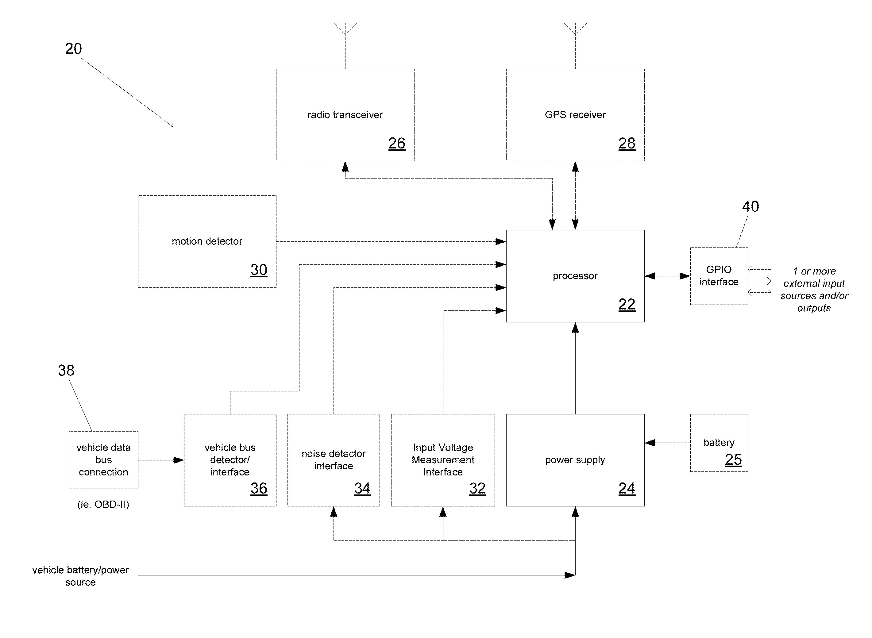
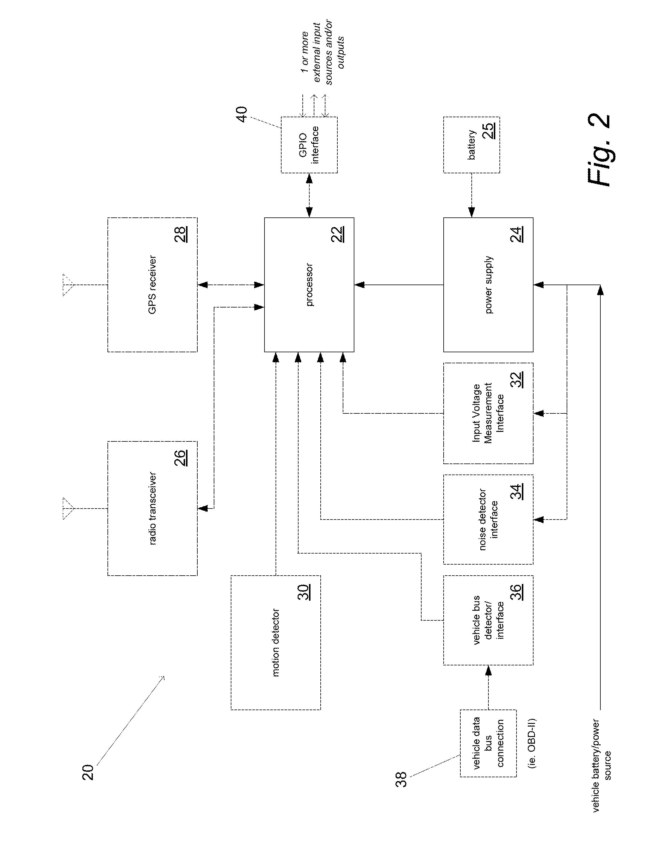
[0006]Systems and methods are described for estimating the ignition state of a vehicle without connecting to the vehicle's ignition line. In a number of embodiments, vehicle telematics systems that do not include direct connections to the vehicle ignition line are configured to determine vehicle ignition state. In several embodiments, aspects of the power supply are monitored to determine the vehicle ignition state, including but not limited to, changes in the voltage on the power supply line, the noise level on the power supply line, and / or the AC coupling on the DC power supply line. In many embodiments, vehicle vibration indicative of ignition status is detected using an accelerometer. In a number of embodiments, rate of voltage transitions (i.e., message frequency) on the OBD or other data bus line is monitored to observe activity indicative of vehicle ignition. Voltage averaging may also be used to observe activity indicative of vehicle ignition. This may include voltage averaging on the OBD or other data bus line monitored to observe activity indicative of vehicle ignition. In many instances, techniques including those outlined above are used in combination with GPS data to determine vehicle ignition status. By eliminating the need to connect to a vehicle ignition line, systems and methods in accordance with embodiments of the invention simplify the installation process and reduce the likelihood that errors in the installation process will negatively impact the performance of the installed device.

Problems solved by technology

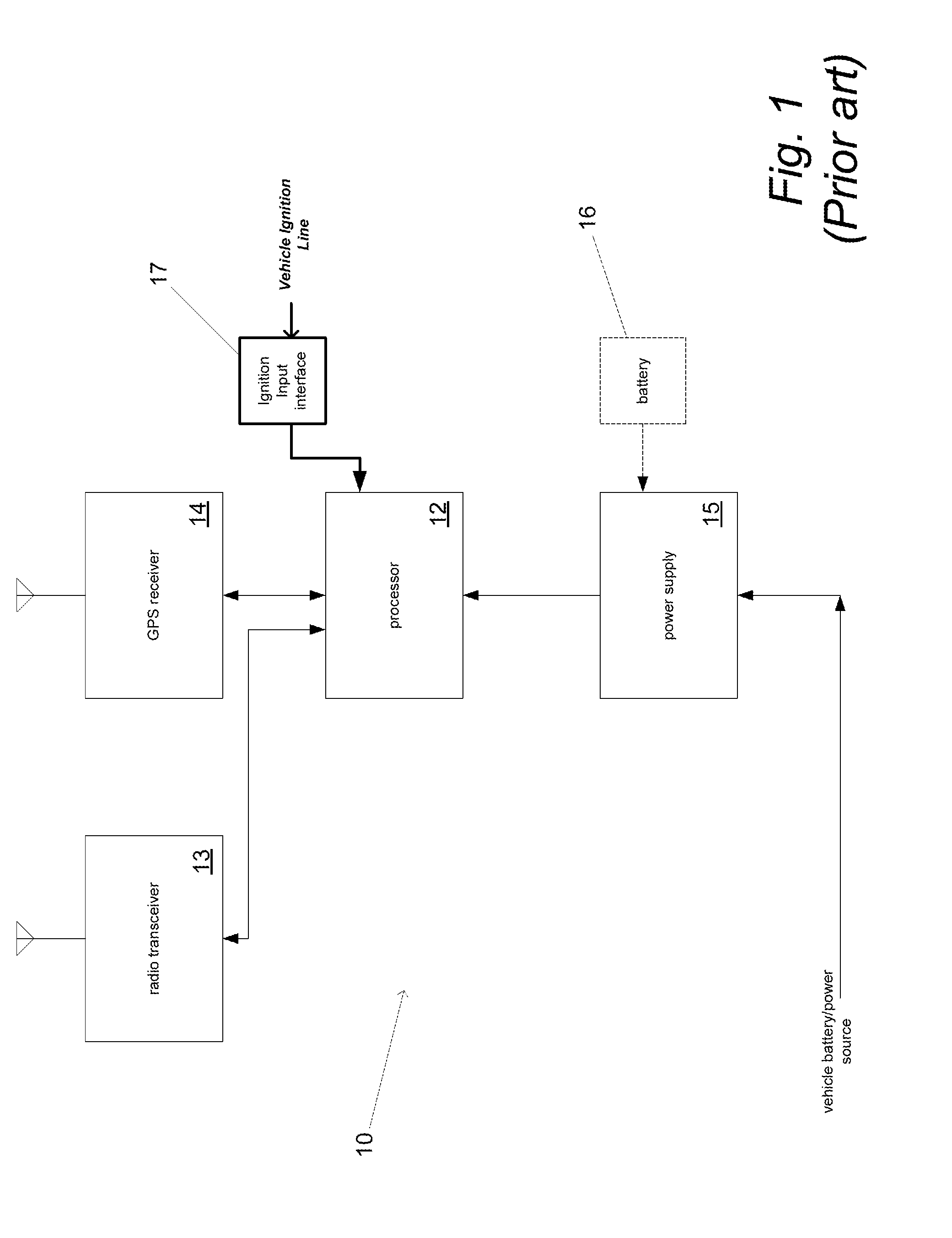
A common problem encountered during installation of devices in a motor vehicle that connect to the vehicle's electrical system is that the installer may inadvertently connect the ignition input interface 17 to a wire that is not the vehicle ignition line.
U.S. Pat. No. 6,163,690, the disclosure of which is incorporated by reference herein in its entirety, notes the potential for the ignition sense line of a hands-free adapter for a mobile phone to be incorrectly connected to a line other than the ignition line due to installer error, which can result in the hands-free adaptor believing the ignition is always on and undesirably draining the vehicle's battery.

Method used


Image

  • Systems and methods for virtual ignition detection
  • Systems and methods for virtual ignition detection
  • Systems and methods for virtual ignition detection

Examples


Embodiment Construction

[0034]Turning now to the drawings, systems and methods for determining vehicle ignition state using a device added to the vehicle after the manufacture of the vehicle without a direct connection to the vehicle ignition line are illustrated. In many instances, the device is installed in a location where the vehicle ignition line is available to the device however the device does not utilize a connection to the vehicle ignition line to simplify installation. In a number of embodiments, vehicle ignition state is ascertained by monitoring the vehicle for signs indicative of the vehicle ignition state without directly connecting to the vehicle ignition line. Information indicative of vehicle ignition state can be ascertained by observing characteristics of the vehicle including but not limited to the power supplied by the vehicle, vehicle vibration, communications on an OBD or other data bus line, and / or vehicle position information. In many embodiments, multiple different types of infor...


PUM


Abstract

Systems and methods for determining vehicle ignition state using a device added to the vehicle after the manufacture of the vehicle without a direct connection to the vehicle ignition line are disclosed. In a number of embodiments, a system includes a processor, a motion detector configured to detect vehicle motion and to enable the processor to obtain motion data, a Global Positioning System (GPS) receiver configured to determine location and to enable the processor to obtain at least speed data, and a radio transceiver configured to communicate with the processor. Additionally, the processor is configured to estimate the ignition state of a vehicle using at least the motion data and the speed data.

Description

RELATED APPLICATIONS[0001]This application claims priority to U.S. Provisional. Application No. 61 / 256,989 filed Oct. 31, 2009 and U.S. Provisional. Application No. 61 / 257,137 filed Nov. 2, 2009, the disclosures of which are incorporated herein by reference.FIELD OF THE INVENTION[0002]The present invention relates generally to vehicle telematics systems and more specifically to the detection of vehicle ignition by a vehicle telematics system.BACKGROUND[0003]A vehicle telematics system is typically a system installed in a vehicle that is capable of determining the location of the vehicle and communicating the vehicle's location to a remote location via a wireless communication link. Vehicle telematics systems are installed in a variety of applications including, but not limited to, fleet management, vehicle finance, vehicle maintenance, driver management, and / or fuel management.[0004]A common configuration for a vehicle telematics system is illustrated in FIG. 1. The vehicle telemati...

Claims


Application Information

Patent Timeline
Patent Type & Authority Patents(United States)
IPC IPC(8): B60L3/04
CPCB60R25/102G06F7/00G07C5/02
Inventor HERGESHEIMER, PETER D.HALL, STEPHENWHITESIDE, JOSEPH BRIAN
Owner CALAMP CORP
Learn More