
Crankcase ventilation system of supercharged gasoline engine and work method of crankcase ventilation system

A technology for crankcase ventilation and gasoline engine, which is applied to crankcase ventilation, engine components, machines/engines, etc., can solve the problems of high heat load, high oil temperature, and large negative value of internal bending pressure of the supercharged gasoline engine, etc. Achieve increased operational reliability, improved exhaust emissions, optimized crankcase ventilation systems

Active Publication Date: 2013-10-23
CHERY AUTOMOBILE CO LTD
View PDF8 Cites 16 Cited by
  • Summary
  • Abstract
  • Description
  • Claims
  • Application Information

AI Technical Summary

Problems solved by technology

[0006] The present invention designs a crankcase ventilation system for a supercharged gasoline engine and its working method, which solves the following technical problems: (1) The fresh air in the intake system of the existing engine crankcase ventilation system cannot enter the inside of the crankcase, It prevents fresh air from participating in the exhaust gas circulation; (2) There is a large vacuum source in the intake manifold, which leads to a large negative value of the internal curvature pressure of the engine, which will damage the sealing surfaces of the engine in severe cases; (3) Heat loads are common in supercharged gasoline engines Too large, high oil temperature, serious problems of oil vaporization and atomization

Method used


Image

  • Crankcase ventilation system of supercharged gasoline engine and work method of crankcase ventilation system

Examples


Embodiment Construction

[0021] Combine below figure 1 , the present invention is further described:

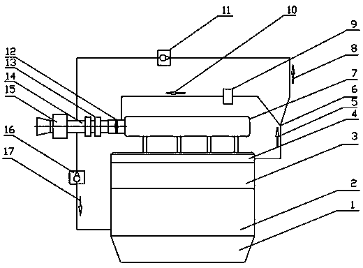
[0022] A crankcase ventilation system for a supercharged gasoline engine, the direction of crankcase exhaust gas at low load: valve chamber cover 4→tee pipe 6→PCV valve 9→intake manifold 7→combustion chamber, air filter 15 and An air supply channel 17 is added between the intake hose 14 between the superchargers 13 and the crankcase, and a check valve 16 for the air supply channel is provided on the air supply channel 17 to supply fresh air to: the intake hose 14 →Air supply channel 16→Air supply channel check valve 16→CrankcaseCylinder block 2→Valve chamber cover 4, the waste gas generated follows the trend of the crankcase exhaust gas during the low load. Crankcase exhaust gas direction under high load: valve chamber cover 4→tee pipe 6→exhaust gas passage check valve 11→intake hose 14→supercharger 13→throttle valve body 12→intake manifold 7 → Combustion chamber.

[0023] When the exhaust gas of...


PUM


Abstract

The invention relates to a crankcase ventilation system of a supercharged gasoline engine and a work method of the crankcase ventilation system. Crankcase waste gas in a low-load state passes through a valve cover (4), a three-way pipe (6), a PCV (positive crankcase ventilation) valve (9), an air inlet manifold (7) and a combustion chamber in sequence; an air supply channel (17) is formed between an air inlet hose (14) and a crankcase; an air supply channel one-way valve (16) is arranged on the air supply channel (17); supplied fresh air passes through the air inlet hose (14), the air supply channel (16), the air supply channel one-way valve (16), the crankcase, an air cylinder body (2) and the valve cover (4) in sequence; generated waste gas passes through the same path as the crankcase waste gas. According to the crankcase ventilation system, the one-way valve is opened to supply the fresh air to the crankcase by the characteristic that the negative crankcase pressure value in the low-load supercharged gasoline engine is excessively high, so that on one hand, an effect of adjusting the crankcase pressure is achieved, and on the other hand, the supplied fresh air has the effects of scavenging and purifying the crankcase waste gas.

Description

technical field [0001] The invention relates to an engine crankcase ventilation system, in particular to a crankcase ventilation system for a supercharged gasoline engine. Background technique [0002] First of all, the current turbocharged gasoline engine winding system generally uses two channels, one channel is connected to the intake manifold, and the other channel is connected to the intake hose. When the engine is under low load and the pressure of the intake manifold is negative, the exhaust gas through the manifold will directly enter the intake manifold; when the engine is under heavy load and the pressure of the manifold is positive, the exhaust gas through the bend will will go through the intake hose end first into the intake hose and then into the intake manifold interior. A one-way valve is arranged at the front end of these two passages, and the fresh air of the intake system cannot enter the inside of the crankcase, which prevents the fresh air from particip...

Claims


Application Information

Patent Timeline
IPC IPC(8): F01M13/00F01M13/02
Inventor 赵友胡涛平徐勇
Owner CHERY AUTOMOBILE CO LTD
Learn More