Spinning take-up device and spinning take-up equipment

A technology of coiling device and spinning device, which is applied in the directions of transportation and packaging, textile and papermaking, and conveying filamentous materials, etc., and can solve the problem of large and complex frame and spinning coiling device, installation and disassembly of silk supply unit Difficult, difficult to form a supporting wire feeding unit and other problems, to achieve the effect of easy adjustment, easy maintenance, and easy installation

Active Publication Date: 2016-08-24
TMT MACHINERY INC
View PDF10 Cites 0 Cited by
  • Summary
  • Abstract
  • Description
  • Claims
  • Application Information

AI Technical Summary

Problems solved by technology

However, since interference between the support member and the thread passage needs to be avoided, the support member cannot be arranged in a space where a plurality of thread passages exist.
That is, since the support member cannot be arranged across the space in which a plurality of yarn passages exist, it is difficult to form the support member in the lower part or near the yarn supply unit arranged near the package forming part and consist of a plurality of threads. The structure of the common support member of the spinning take-up device
In addition, although it is conceivable to dispose the support member at a position higher than the roller provided at a high place above the package forming part, in this case, the position of the support member is very high, so the installation of the wire supply unit, Disassembly becomes difficult, and the spinning take-up device itself becomes larger
[0006] On the other hand, although it is also possible to support the yarn supply unit on the frame protruding from the back side of the spinning take-up device, since the support member is moved from a position away from the yarn supply unit arranged on the front side of the spinning take-up device Stretch out, so the frame and spinning take-up device are enlarged and complicated
In addition, the support member that can be used in common by multiple spinning take-up devices can only be installed at a position that does not interfere with the yarn passage from the yarn supply unit to the package forming part, so it cannot be erected near the yarn supply unit. Common parts make it difficult to form a structure that supports the wire feeding unit with common parts

Method used


Image

  • Spinning take-up device and spinning take-up equipment
  • Spinning take-up device and spinning take-up equipment
  • Spinning take-up device and spinning take-up equipment

Examples


Embodiment 1

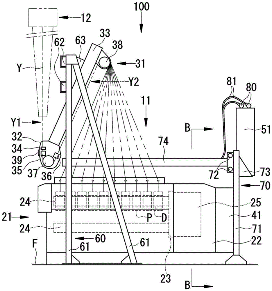
[0049] use Figure 1 to Figure 5 The spinning winding device 11 according to the first embodiment of the present invention and the spinning winding facility 100 configured by arranging a plurality of spinning winding devices 11 in a row will be described. In the following description, the free end side of the bobbin holder 24 to be described later will be referred to as the front side of the spinning winding device 11, and the opposite side thereof will be referred to as the rear side. A side surface of the spinning winding device 11 is defined as a surface viewed from the side of the bobbin holder 24 . In addition, the up-down direction refers to the up-down direction in a state in which the spinning winding device 11 is installed on a horizontal plane.

[0050] First, refer to figure 1 , figure 2 The spinning device 12 that supplies the yarn Y to the spinning take-up device 11 will be described. The spinning device 12 is a device that spins a plurality of filaments and ...

Embodiment 2

[0089] Second, use Figure 6 and Figure 7 The spinning winding device 11 according to the second embodiment of the present invention and the spinning winding device 100 configured by arranging a plurality of spinning winding devices 11 in a row will be described. The spinning take-up device 11 according to the present embodiment is a spinning take-up device for FDY that takes up FDY (drawn yarn). The detailed description of the configuration common to the first embodiment is omitted.

[0090] Such as Figure 6 as well as Figure 7 As shown, the spinning winding device 11 of this embodiment includes a yarn supply unit 31 . The yarn supply unit 31 of the spinning take-up device for FDY is a device that feeds the yarn Y toward the package forming unit 21 while heat-treating the plurality of yarns Y spun from the spinning device 12 . In the yarn supply unit 31, in addition to the first roller 37 and the second roller 38, a plurality of yarn processing rollers 91 to 96 are co...


PUM


Abstract

[OBJECT] A yarn feeding unit of a take-up apparatus can readily be arranged, so as to facilitate ease of installation and maintenance for the take-up apparatus. [MEANS OF REALIZING THE OBJECT] A take-up apparatus includes a package winding unit (21), a first godet roller (37), a second godet roller (38) arranged above the package winding unit (21) and more on the downstream side than the first godet roller (37) in the travel direction of the yarns, a yarn feeding unit (31) including the first godet roller (37) and the second godet roller (38) and configured to feed the yarns Y from a melt spinning machine (12) to the package winding unit (21) while processing the yarns, and a first beam (62) disposed in an area sandwiched by a first yarn path (Y1) between the melt spinning machine (12) and the first godet roller (37) and by a second yarn path (Y2) leading from the first godet roller (37) to the second godet roller (38) and configured to support the yarn feeding unit (31).

Description

technical field [0001] The present invention relates to a spinning take-up device and a spinning take-up device for winding a yarn spun by a spinning device into a take-up bobbin. Background technique [0002] The spinning take-up device is used to wind up a plurality of yarns spun by the spinning device on a plurality of take-up bobbins. Furthermore, the spinning and winding facility is constituted by arranging a plurality of spinning and winding devices in a row. The spinning take-up device is provided with a package forming section that winds the yarn around the take-up bobbin. Various devices, such as rollers, yarn guides, and yarn cutting and suction devices, are installed near the package forming section for feeding the yarn from the spinning device to the package forming section while processing it. [0003] The above-mentioned devices installed in the vicinity of the package forming section are separately installed on the frame constituting the spinning winding dev...

Claims


Application Information

Patent Timeline
Patent Type & Authority Patents(China)
IPC IPC(8): D01D7/00
CPCB65H67/048B65H51/06B65H51/32B65H54/70B65H57/003B65H2701/3132
Inventor 桥本欣三岸根章典
Owner TMT MACHINERY INC
Why Eureka
Try Eureka