Eureka AIR delivers breakthrough ideas for toughest innovation challenges, trusted by R&D personnel around the world.

Automobile A pillar perspective vehicle-mounted display device

A vehicle-mounted display and automobile technology, applied in optical observation devices, vehicle parts, transportation and packaging, etc., can solve problems such as poor prediction results, potential safety hazards, and inability to correctly estimate the driver's direction, so as to eliminate overlap and redundancy. redundancy, improved safety and convenience, and the effect of good driver acceptance

Active Publication Date: 2013-10-23
固安海高汽车技术有限公司
View PDF7 Cites 57 Cited by
  • Summary
  • Abstract
  • Description
  • Claims
  • Application Information

AI Technical Summary

Problems solved by technology

[0003] Most of the existing A-pillar visual barrier elimination devices install the display on the inner side of the A-pillar and mostly use a liquid crystal display, which cannot completely fit the A-pillar, and cannot intelligently adjust the observation screen, or manually press the display button to adjust the outside of the vehicle. Scene images, not only distracting and time-consuming during debugging, but also pose safety hazards in emergency situations
Someone proposes to use the distance sensor to detect the distance between the driver's body and the screen to adjust the display screen. Although it solves the potential safety hazard without manual operation, the prediction effect is not good, the accuracy drops, and it is impossible to correctly estimate the direction the driver is really looking at.

Method used


Image

  • Automobile A pillar perspective vehicle-mounted display device
  • Automobile A pillar perspective vehicle-mounted display device
  • Automobile A pillar perspective vehicle-mounted display device

Examples


Embodiment Construction

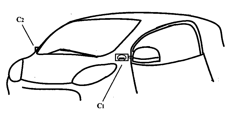
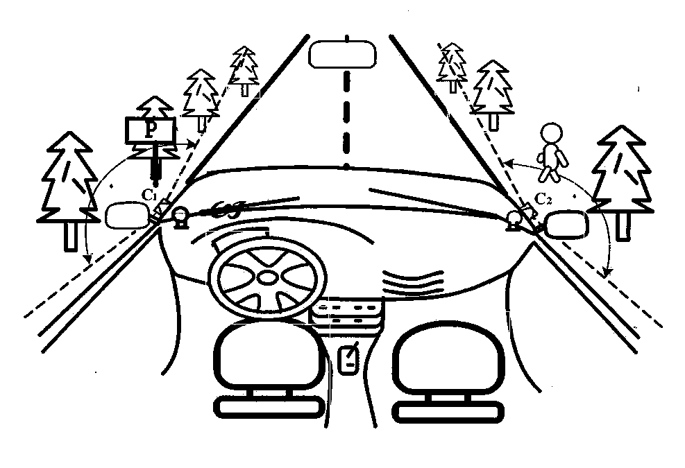
[0018] Such as Figure 4 As shown, in this embodiment, the first flexible liquid crystal display A1 and the second flexible liquid crystal display A2 with the same area radian are respectively arranged on the slopes on both sides of the A-pillar in the car, and the first flexible liquid crystal display A1 and the second flexible liquid crystal display The input end of the screen A2 is connected to the information processing control unit, and the information processing unit is realized by the vehicle-mounted computer. The first camera B1 and the second camera B2 are respectively installed at the bottom of the first flexible liquid crystal display A1 and the second flexible liquid crystal display A2 on both sides of the A-pillar in the car to collect the driver's visual information (pupil position and corneal reflection parameters). Calculate the driver's gaze focus angle β in the world coordinate system through the driver's eye movement parameters collected by the first camera ...


PUM


Abstract

The invention discloses an automobile A pillar perspective vehicle-mounted display device which reflects dynamic changes of driver sight angles. Cameras are arranged both inside an automobile and outside the automobile, the cameras outside the automobile are used for collecting surrounding sight information of a road ahead, and the cameras inside the automobile are used for obtaining driver vision information; according to driver sight concerning angles, images concerned by a driver are cut from images obtained by the cameras outside the automobile; flexible liquid crystal display screens are arranged on the inner side of an A pillar in an attaching mode according to the radian of the A pillar to display images; the images displayed on the flexible liquid crystal display screens inside the automobile are changed in real time according to driver sight angle change information collected by the cameras inside the automobile; the angle and the size of a driving scene image, collected by the cameras outside the automobile, at the position of a blind region are changed in real time, and an A pillar display system can be adjusted in a self-adaption mode according to sight needing regions detected through sight tracking. Therefore, external road traffic environment information which is more complete, more accurate and good in driver acceptability is provided for the driver, and the safety and the convenience of automobile driving are improved.

Description

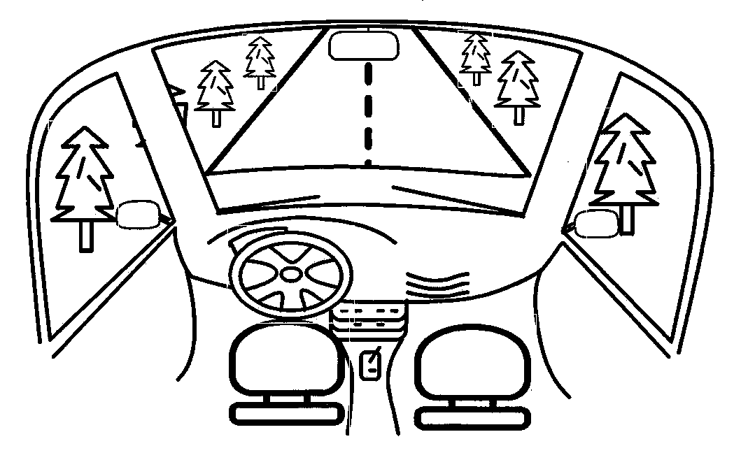
technical field [0001] The invention relates to an automobile safety device, in particular to an on-vehicle image display system which reflects the dynamic change of the driver's sight angle and makes the A-pillar transparent. Adaptively adjust the angle and size of the screen in real time according to the needs of the driver's attention area, so that it is more convenient and quick to obtain driving surround view information. Background technique [0002] The pillar between the windshield and the front door of the car is called the A-pillar. Because the A-pillar will block the driver's part of the line of sight during driving, it will cause a visual blind spot, such as figure 1 shown. The existence of the A-pillar blind spot is one of the important causes of traffic accidents. The inconvenience of sight blocking is more obvious especially when the driver is turning or changing lanes. Therefore, we hope that the narrower the A-pillar, the better, and the A-pillar supports t...

Claims


Application Information

Patent Timeline
Patent Type & Authority Applications(China)
IPC IPC(8): B60R1/00H04N7/18B60R11/02B60R11/04
Inventor 高镇海李扬高菲张利丹段立飞
Owner 固安海高汽车技术有限公司
Why Eureka
Eureka Blog
Learn More