
Method for bending bridge U-shaped rib in ignition general yield manner by adopting special clamping device

A clamping device and U-shaped technology, which is applied in the field of bridge manufacturing, can solve the problems that the deformation cannot be transmitted to the other side, the U-shaped rib cannot be bent, and the U-shaped rib cannot be deformed, so as to achieve low investment, high production efficiency, and easy operation. easy effect

Active Publication Date: 2015-01-07
HAIOD HEAVY ENG TECH
View PDF6 Cites 0 Cited by
  • Summary
  • Abstract
  • Description
  • Claims
  • Application Information

AI Technical Summary

Problems solved by technology

Before the present invention, U-shaped ribs were difficult to bend, and they were bent by machinery. At present, there is no machine specially designed for U-shaped ribs
It can only be bent by pyrotechnics, but U-shaped ribs cannot be bent by traditional pyrotechnic bending methods.
From the perspective of the principle of pyrotechnic bending, pyrotechnic bending is mainly to heat one side of the bent body, so that the heat shrinkage deformation of one side is transmitted to the other side; but because the U rib is open and the wall is too thin, the deformation It cannot be passed to the other side, and the U rib cannot be deformed as a whole

Method used


Image

  • Method for bending bridge U-shaped rib in ignition general yield manner by adopting special clamping device
  • Method for bending bridge U-shaped rib in ignition general yield manner by adopting special clamping device
  • Method for bending bridge U-shaped rib in ignition general yield manner by adopting special clamping device

Examples


Embodiment 1

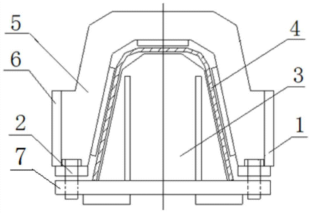
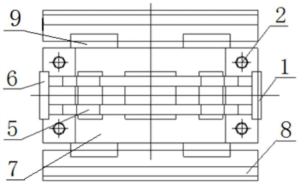
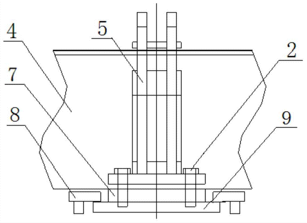
[0027] Embodiment 1: A special clamping device for bending U-shaped ribs provided by the present invention, its structure is as follows figure 1 , 2 Shown in and 3, include inner template 3, outer die 5, guide rail 8 and base plate 7, described inner template is welded on the base plate, base plate 7 is welded on the slider 9, inner template 3, base plate 7 and slider 9 Formed in one piece, slide in the guide rail 8 together. The outer die 5 is covered outside the inner template. When the special clamping device is used, the inner template 3 is covered in the U-shaped rib to be bent, and the outer die 5 and the inner template 3 are correspondingly installed outside the U-shaped rib to be bent. The lower ends of both sides of the outer die 5 are respectively processed with 2 bolt holes, the outer die 5 is fixed on the bottom plate 7 by bolts 2, and the two ends of the outer die 5 are equipped with a pressure plate 1 and a baffle plate 6 respectively; A jack 11 is installed on...

Embodiment 2

[0037] Embodiment 2: The present invention provides a kind of method that adopts the special clamping device described in embodiment 1 pyrotechnic full yield to bend the method for bridge U-shaped rib, bends a 16 meters long, plate thickness 8 millimeters, bottom width 300 millimeters , U-shaped ribs for bridges with a height of 280 mm, its operation steps are basically the same as in embodiment 1, the difference is that a U-shaped rib bending work platform is formed by 7 workbenches 13, and each workbench is spaced at 2.2 meters. When each hot bending point section is heated one by one, the temperature of the flame drying gun is controlled at 830-890°C, and the heating time of the drying gun is 30 seconds, so that the entire section of the heating can reach above 800°C at the same time. Full yield; each section of the hot bending point is pyrotechnically heated one by one, and then cooled sequentially to make the entire U-shaped rib bend and shape.

[0038] The special U-shap...


PUM


Abstract

The invention relates to a method for bending bridge U-shaped ribs in an ignition general yield manner by adopting a special clamping device. The clamping device comprises an inner formwork, an outer stamper, a guide rail and a baseplate, wherein the inner formwork, the baseplate and sliding blocks are welded into a whole to slide on the guide rail; the inner formwork is covered with the outer stamper; the lower end of the outer stamper is fixed on the baseplate through bolts; a bearing plate and a baffle are mounted at the two ends of the outer stamper respectively; a jack is mounted on the outer side of the bearing plate end; a support base is mounted on the outer side of the baffle end; the jack, the support base and the guide rail are fixed on the working platform. The method for bending U-shaped ribs comprises the following steps: the clamping device clamps a U-shaped rib at a certain interval, the whole U-shaped rib is divided into several heating bended sections, the jack applies force to the U-shaped rib to pre-deform the U-shaped rib, the heating bended sections are heated by an ignition stoving gun point by point and cooled in sequence, so as to enable the whole U-shaped rib to be curved into the preset radian. The method is simple and convenient in operation, low in investment, low in energy source consumption, high in bending precision and production efficiency, and has extensive popularization value.

Description

technical field [0001] The invention relates to a method for bending U-shaped ribs of a bridge by pyrotechnic full-yield bending of a special clamping device, which belongs to the field of bridge manufacturing. Background technique [0002] The U-shaped rib is the stiffener of the orthotropic deck of the steel bridge. It is an important component of the bridge. The U-shaped rib usually used is straight when processed, with a length of several meters to more than ten meters, a plate thickness of 6-8 mm, and a bottom width of 300 mm. , about 280 mm high, with a U-shaped section. But in the curved bridge shape, the U-shaped rib needs to be bent into an arc along with the bridge shape. In the bridge factory manufacturing process, the straight U-shaped ribs need to be bent into arcs. Many bridge factories have encountered technical difficulties in bending U-ribs. Before the present invention, U-shaped ribs were difficult to bend, and were bent by machinery, and there was no ma...

Claims


Application Information

Patent Timeline
Patent Type & Authority Patents(China)
IPC IPC(8): B21D7/16B21D7/00
Inventor 宋雄文叶顺答浩陈复保
Owner HAIOD HEAVY ENG TECH
Learn More