


Quick Research
Generate reliable direction feasibility study reports for your R&D in just a few steps.

Technical Q&A
Discover and master advanced knowledge NOW. Basics, ideas, possibilities, all at once.

Find Solutions
As an expert in R&D theories, this can generate solutions to your technical problems instantly.

Evaluate Feasibility
Analyze your overall solution with one click, know your potential R&D risks in advance.

Monitor Landscape
Get weekly tech updates, stay abreast of the latest tech innovations and key insights.
Plasma hand sterilizer
A sterilizer, plasma technology, applied in electrotherapy, treatment and other directions, can solve the problem of not being able to achieve complete hand disinfection
- Summary
- Abstract
- Description
- Claims
- Application Information
AI Technical Summary
Problems solved by technology
Method used
Image

Examples
Embodiment Construction
[0010] The present invention will be further illustrated below in conjunction with the accompanying drawings and specific embodiments. This embodiment is implemented on the premise of the technical solution of the present invention. It should be understood that these embodiments are only used to illustrate the present invention and are not intended to limit the scope of the present invention.
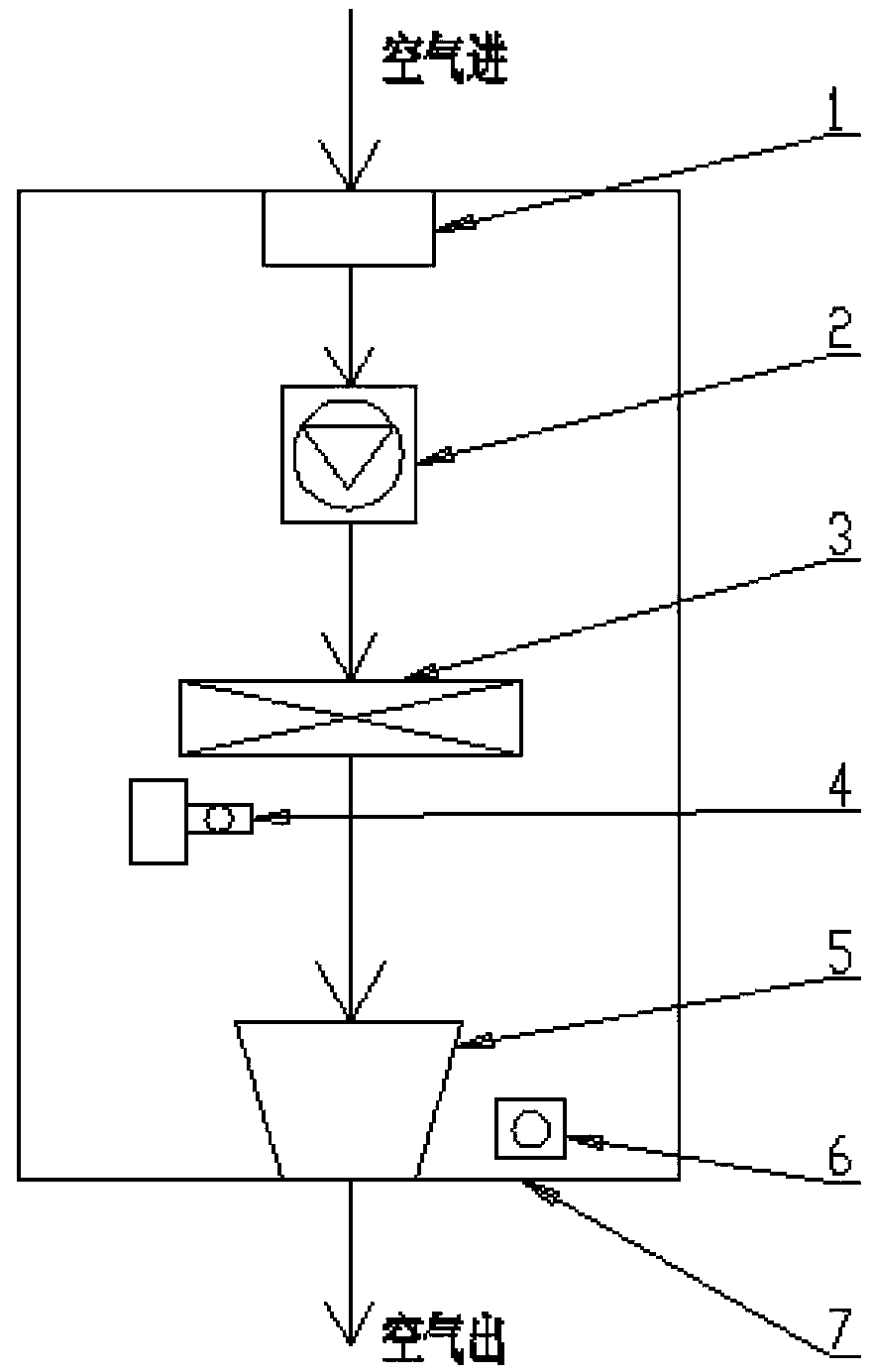
[0011] Such as figure 1 As shown, a plasma hand disinfection machine includes an air inlet 1, a fan 2, a filter 3, a plasma generator 4, a jet outlet 5, an induction switch 6 and a housing 7 for installing all the above components.
[0012] The air inlet 1, the fan 2, the filter 3 and the air outlet 5 are connected sequentially from top to bottom in the casing 7, the plasma generator 4 is arranged between the filter 3 and the air outlet 5, and the induction switch 6 is arranged at the outlet. Next to the tuyere 5.
[0013] When the sterilizer is working, the air is first sucked in by t...
PUM
 Abstract
Description
Claims
Application Information
 - R&D Engineer
- R&D Manager
- IP Professional
- Industry Leading Data Capabilities
- Powerful AI technology
- Patent DNA Extraction
Browse by: Latest US Patents, China's latest patents, Technical Efficacy Thesaurus, Application Domain, Technology Topic, Popular Technical Reports.
© 2024 PatSnap. All rights reserved.Legal|Privacy policy|Modern Slavery Act Transparency Statement|Sitemap|About US| Contact US: help@patsnap.com