Automatic four-station three-process feeding mechanism

An automatic feeding and process technology, applied in the direction of manufacturing tools, metal processing equipment, feeding devices, etc., can solve the problems of scattered arrangement of three rolling machines, extended production line layout, and insufficient compactness, so as to save work auxiliary time, The effect of fast production rhythm and reasonable structure

Active Publication Date: 2013-10-16
SHANDONG XIAOYA PRECISE MACHINERY
View PDF7 Cites 6 Cited by
  • Summary
  • Abstract
  • Description
  • Claims
  • Application Information

AI Technical Summary

Problems solved by technology

The scheme is carried out one by one through the principle of the conveyor belt. This method has a complex structure and inevitably requires the layout of the production line to be extended. The arrangement of the three rolling machines is scattered and not compact enough.

Method used


Image

  • Automatic four-station three-process feeding mechanism
  • Automatic four-station three-process feeding mechanism
  • Automatic four-station three-process feeding mechanism

Examples


Embodiment 1

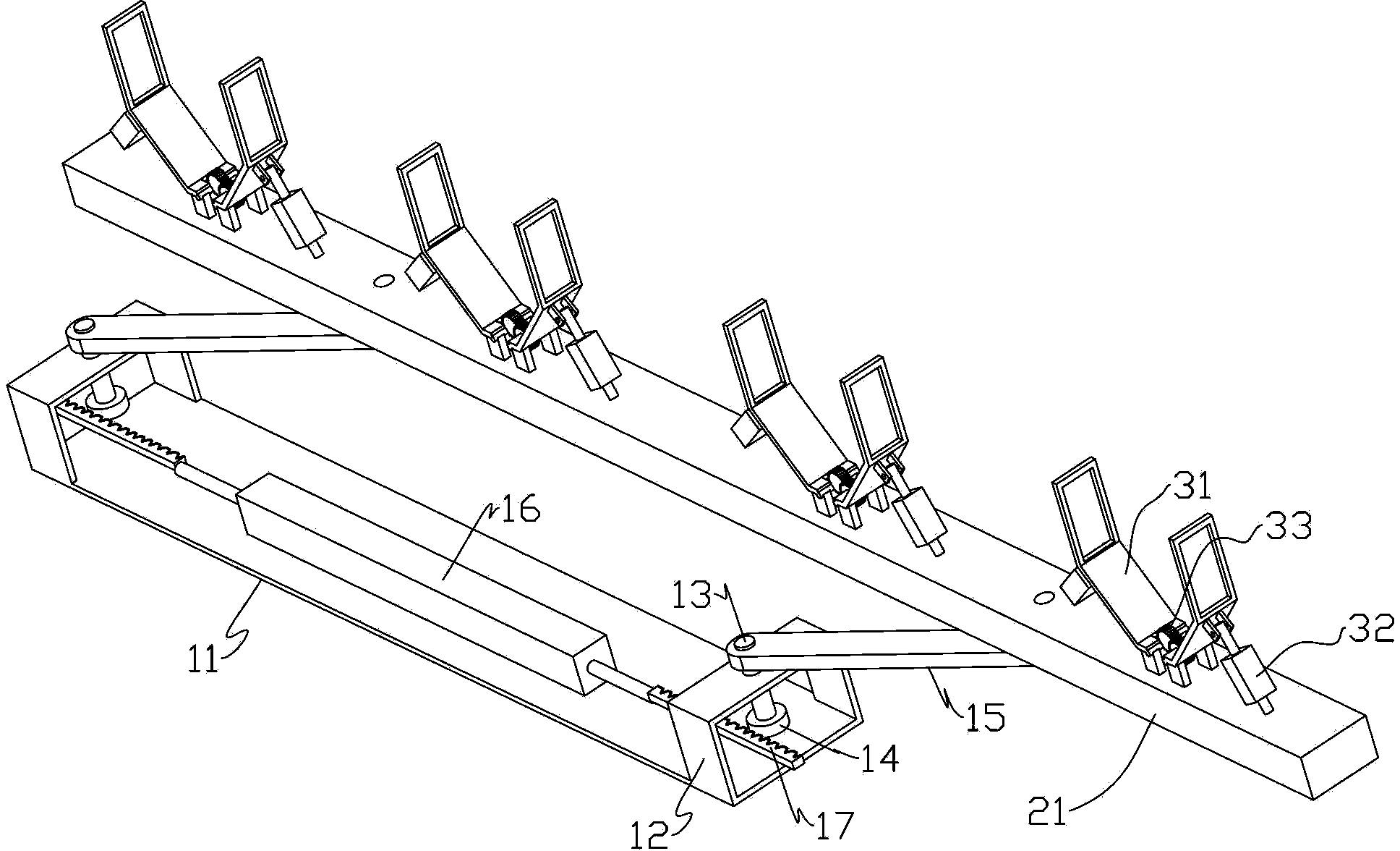
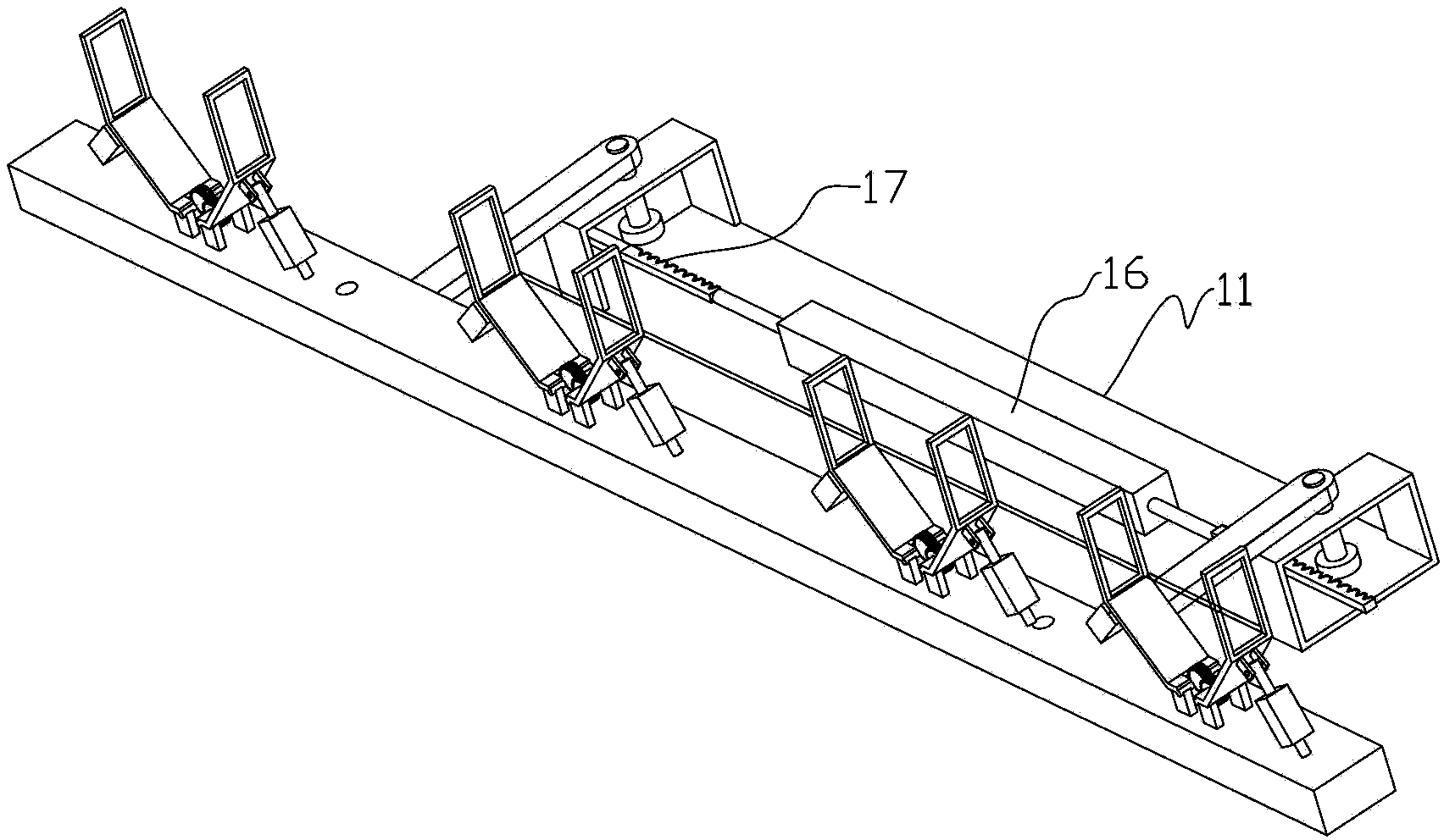
[0021] Embodiment one, such as Figure 1 to Figure 4 As shown, a four-position three-process automatic feeding mechanism includes a base, a feeding frame beam, a connecting rod and a clamping device. Wherein the base 11 is a mounting platform for other parts, and the bottom is provided with wheels. The wheels preferably have universal wheels with a locking function, so that they can be moved easily, and can be locked to fix them in one position. These are prior art means, no more details.

[0022] First, there are two horizontal plates and two mounting blocks 12 in the base 11, and the two mounting blocks are located at the front and rear ends of the base, and each mounting block 12 is respectively provided with a vertical shaft hole, and each shaft hole A rotating shaft 13 is installed in the middle, and in order to improve the lubricating performance, a bearing bush is installed between the two. The upper and lower ends of the rotating shaft are respectively fixed with a g...

Embodiment 2

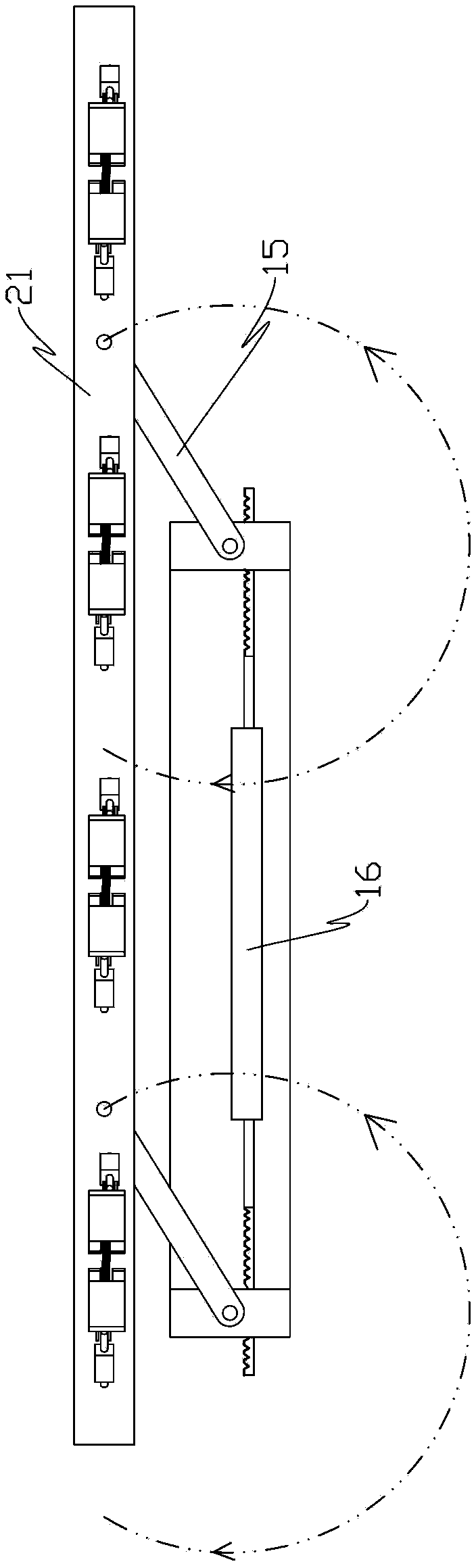
[0029] like Figure 5 As shown, the difference from Embodiment 1 is that a rocker arm 41 and a connecting rod are respectively fixed at the upper and lower ends of the rotating shaft, and the other end of the connecting rod is pivotally connected to the beam of the loading rack, the beam of the loading rack, the base and two The pivot joints between the connecting rods form a parallelogram linkage mechanism, and a power source is installed between the rocker arm and the base, and the power source driving the deformation of the parallelogram linkage mechanism is a two-way oil cylinder or an air cylinder; the force is realized through the rocker arm. transmission.


PUM


Abstract

An automatic four-station three-process feeding mechanism comprises a base, a feeding frame beam, connecting rods and clamping devices. The front end and the rear end of the base are respectively provided with a vertical shaft hole, a rotating shaft is installed in each shaft hole, a rocker arm and one connecting rod are respectively fixed at the upper end and the lower end of each rotating shaft, the other ends of the connecting rods are connected to the feeding frame beam in a pivot mode, the pivot points among the feeding frame beam, the base and the two connecting rods form a parallelogram connecting mechanism, a power source is installed among the rocker arms and the base, and the four clamping devices are evenly arranged on the upper side of a feeding frame from front to rear at equal intervals. The parallelogram connecting mechanism is fast in transposition production rhythm and high in production efficiency and saves working auxiliary time effectively; the four-connecting-rod structure is adopted for the whole structure, in feeding and discharging processes, receding action exists between the feeding mechanism and a main shaft of a roll forming machine, and the feeding mechanism can automatically conveying rim blanks to the main shaft and is reasonable in structure, accurate, and high in stability.

Description

technical field [0001] The invention relates to the technical field of a rim rolling machine production line, in particular to a four-position three-process automatic feeding mechanism. Background technique [0002] The manufacturing process of the wheel rim is to first roll the plate into a circle and weld it into a cylindrical structure, and then form the required end face shape of the rim through several times of rolling forming, and finally expand to improve the accuracy. The rolling process generally needs to go through Three times, that is, primary rolling, secondary rolling and triple rolling, and the commonly used equipment is rolling machine. In the current production line, there is no linkage design between the three roll forming machines, that is to say, the completion of the first roll forming needs to be carried to the second roll forming machine station manually or by a mechanical arm, and then transported to the third roll forming machine after completion Rol...

Claims


Application Information

Patent Timeline
IPC IPC(8): B21H9/00
Inventor 孙豪坤徐坤李振兵宋志强殷治胜杨翠张型亮
Owner SHANDONG XIAOYA PRECISE MACHINERY
Why Eureka
Try Eureka