Relay device

一种中继装置、信息包的技术,应用在数字传输系统、电气元件、传输系统等方向,能够解决虚拟信道个数或尺寸大等问题,达到低延迟、改善传输性能的效果

Active Publication Date: 2013-10-09
PANASONIC INTPROP MANAGEMENT CO LTD
View PDF6 Cites 2 Cited by
  • Summary
  • Abstract
  • Description
  • Claims
  • Application Information

AI Technical Summary

Problems solved by technology

[0067] In this regard, since multiple relay devices need to be configured on an integrated circuit in the NoC, compared with a parallel computer or an ATM network relay device, the number or size of virtual channels that can be configured on each relay device cannot be adjusted. set larger

Method used


Image

  • Relay device
  • Relay device
  • Relay device

Examples


Embodiment approach 1

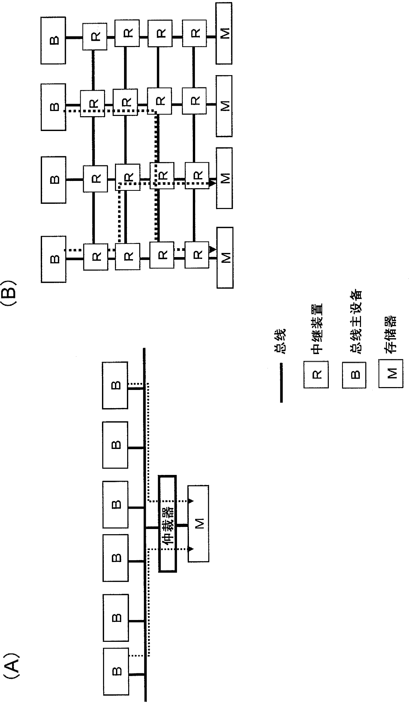
[0130] Figure 6 It is a figure explaining the outline|summary of the operation|movement of the relay apparatus of this embodiment. The master device A and the master device B are connected to a common memory via the relay device A and the relay device B on the NoC. Shows the situation where master device A and master device B respectively send packets to the memory.

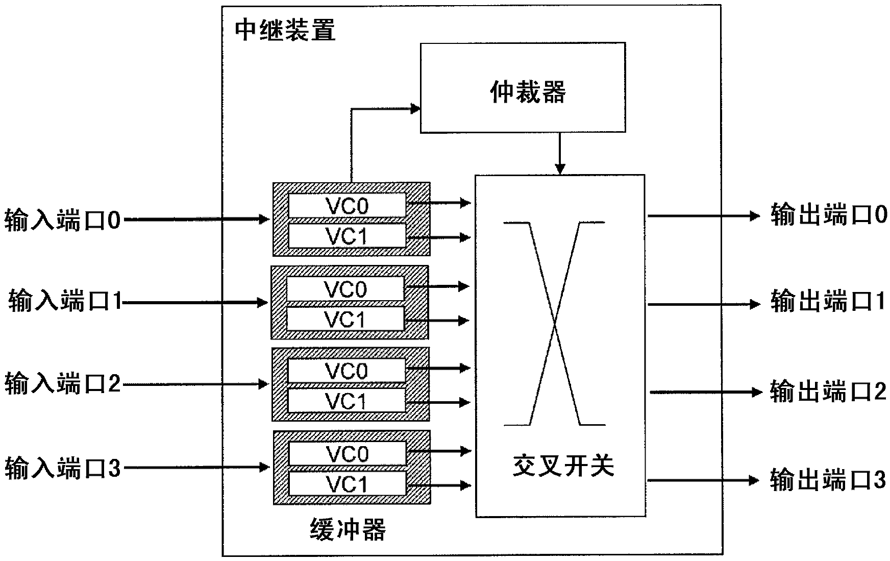
[0131] The relay device A and the relay device B respectively have two input ports and output ports, and each input port has four virtual channels (VCs).

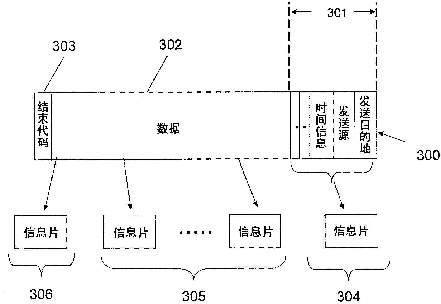
[0132] The relay device according to the present embodiment refers to the sending node of the packet transmitted by the allocated virtual channel when performing allocation (VA) of the virtual channel. Then, when a packet (information piece) is received from a plurality of transmission nodes, at least one virtual channel ( VA). In other words, assign one or more virtual channels (VA) of relay devices to each source, so that packets sent from a certain sen...

Embodiment approach 2

[0277] In Embodiment 1, in the relay device mounted on the semiconductor circuit where there are restrictions on the number or size of virtual channels, it is assumed that the relay device distinguishes the transmission node of the packet to be transmitted, and the information of each transmission node The packet is assigned one or more virtual channels as relay devices of adjacent receiving nodes. As a result, a state in which transmission scheduling can be performed for a plurality of packets arriving from different transmission nodes is maintained, and the transmission efficiency (throughput or transmission delay) is improved.

[0278] In this embodiment, when the transmission efficiency of the packet is different for each transmission node, the relay device adjusts the transmission efficiency in the relay device that is an adjacent receiving node according to the congestion state of the packet from each transmission node. The number of allocated virtual channels improves t...


PUM


Abstract

The router is used to relay a packet to be transmitted from one node to another in an integrated circuit that has distributed buses according to a packet exchange method. The router includes: a plurality of buffers, each of which configured to store packets with information indicating their transmission node; a classifying section configured to classify the buffers that store the packets into a number of groups according to the transmission nodes of the packets; a selecting section configured to select at least one of the buffers of each group; and an output port configured to sequentially output the packets that are stored in the selected buffer.

Description

technical field [0001] The present invention relates to a technique for adjusting transmission scheduling of a plurality of traffic transmitted between a plurality of relay devices connected between buses in a semiconductor integrated circuit having distributed buses. In particular, the present invention relates to a technique for controlling transmission of packets held in buffers when packets constituting different services are scattered and held in a plurality of buffers. Background technique [0002] figure 1 (A) shows an example of centralized bus control. In an existing integrated circuit that performs centralized bus control, a plurality of bus masters and memory are mainly connected through one bus, and an arbiter (arbiter) mediates access from the bus master to the memory. . However, due to the high functionality and multi-core of integrated circuits, the scale of the circuit increases, and the traffic flows through the bus in complex changes, making the design o...

Claims


Application Information

Patent Timeline
Patent Type & Authority Applications(China)
IPC IPC(8): H04L12/861
CPCH04L49/9047H04L12/4015H04L49/9036
Inventor 吉田笃石井友规山口孝雄
Owner PANASONIC INTPROP MANAGEMENT CO LTD
Why Eureka
Try Eureka