
Mesh opening shell cover and forming method tehreof

A molding method and mesh technology, applied in the direction of cabinets/cabinets/drawer parts, etc., can solve the problems of complex steps, long molding time, and unfavorable long-term development of enterprises, and achieve increased sensitivity, simple structure, and high-quality products. The effect of appearance diversification

Inactive Publication Date: 2013-10-09
AOJIE HARDWARE JIANGSU
View PDF3 Cites 7 Cited by
  • Summary
  • Abstract
  • Description
  • Claims
  • Application Information

AI Technical Summary

Problems solved by technology

The steps of such a molding method are relatively complicated, and the molding time is relatively long, which is not conducive to the long-term development of the enterprise.

Method used


Image

  • Mesh opening shell cover and forming method tehreof
  • Mesh opening shell cover and forming method tehreof
  • Mesh opening shell cover and forming method tehreof

Examples


Embodiment 1

[0041] The molding method of mesh shell cover, comprises steps:

[0042] (a) preparatory process: select the required stainless steel material for making grille 1;

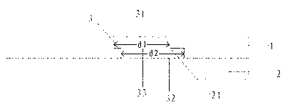
[0043] (b) Dislocation double-sided etching: the stainless steel material is subjected to double-sided etching treatment, so that a mesh 3 is formed on the stainless steel material, such as figure 1 The front hole 31 and the back hole 32 of the shown mesh 3 are circular holes, the front hole 31 of the mesh 3 has an aperture diameter of 0.3mm, and the back hole 32 has an aperture of 0.5mm, and the front hole 31 and the back hole 32 are dislocated Distribution, a back hole 32 corresponds to a front hole 31, the intersection of the front hole 31 and the back hole 32 is a through hole 33, the cross-sectional area of ​​the through hole 33 is 94% of the cross-sectional area of ​​the front hole 31, and the mesh 3 forms Snap-shaped cavity;

[0044] (c) stamping forming: the stainless steel material described in step (b...

Embodiment 2

[0050] A method for forming a mesh shell cover, comprising the steps of:

[0051] (a) preparatory process: select the required stainless steel material for making grille 1;

[0052] (b) Dislocation double-sided etching: the stainless steel material is subjected to double-sided etching treatment, so that a mesh 3 is formed on the stainless steel material, such as image 3 The front hole 31 of the mesh 3 is a circular hole, and the back hole 32 is an oval hole. The front hole 31 of the mesh 3 has an aperture diameter of 0.3mm, and the back hole 32 has an elliptical aperture of 1.15mm*0.45mm. The front hole 31 and the back hole 32 are misplaced, so that the mesh 3 forms a snap-shaped cavity, and one back hole 32 corresponds to two front holes 31, and the intersection of the front hole 31 and the back hole 32 is a through hole 33, and the through hole 33 The cross-sectional area is 87% of the cross-sectional area of ​​the front hole 31, and the mesh 3 forms a buckle-shaped cavity...


PUM

PropertyMeasurementUnit
pore sizeaaaaaaaaaa
thicknessaaaaaaaaaa
melting pointaaaaaaaaaa

Abstract

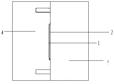
The invention discloses a mesh opening shell cover which comprises a mesh enclosure and a plastic cement layer. The plastic cement layer is arranged on the lower portion of the mesh enclosure, mesh openings are uniformly distributed in the mesh enclosure, protruding blocks are arranged on the plastic cement layer and embedded in the mesh openings, and the mesh enclosure is fixedly connected with the plastic cement layer. A forming method of the mesh opening shell cover includes the steps of process preparation, dislocation double-sided etching, punch forming, surface treatment, injection molding in a die, and demolding. The openings in the obverse side and the openings in the reverse side of the mesh openings are distributed in a staggered mode, and the protruding blocks of the plastic cement layer are embedded in the mesh openings, so the mesh enclosure is fixedly connected with the plastic cement layer, binding agents which must be used for fixed connection in the traditional industry are eliminated, and not only is environment protected, but also fixing effects are good. In addition, because firstly the mesh enclosure is formed through punching, the surface of the mesh enclosure is treated, and then plastic cement raw materials after hot melting are permeated in the mesh openings of the mesh enclosure, keying strength is enhanced, and fixed connection of the mesh enclosure and the plastic cement layer is achieved. The forming method has simple procedures and remarkably beneficial effects.

Description

technical field [0001] The invention relates to an injection molding process, in particular to an injection molding process combining metal materials and plastics. Background technique [0002] There are currently three types of housing covers for electrical appliances on the market: 1. The housing cover is made of plastic; The shell cover is formed by gluing. Among them, the shell cover made of plastic, due to the material characteristics of the plastic itself, has the disadvantages of poor hardness, no metal texture, single color, etc., and the market share is not large; Although the shell cover assembled together has strong hardness, it requires high precision of metal parts and plastic parts, and unqualified products are prone to appear in the production process, the yield rate is poor, the work efficiency is low, and the production cost is correspondingly high, which is not conducive to enterprises. The long-term development of the long-term development; the shell cov...

Claims


Application Information

Patent Timeline
Patent Type & Authority Applications(China)
IPC IPC(8): H05K5/03B29C45/14B29B11/00
CPCB29C45/14336B29C45/14311B29C2045/14327B29K2705/00
Inventor 施碧溪
Owner AOJIE HARDWARE JIANGSU
Learn More