Eureka AIR delivers breakthrough ideas for toughest innovation challenges, trusted by R&D personnel around the world.

Automatic verification system of low-voltage current transformer

A low-voltage current and transformer technology, applied in the field of power metering device testing systems, can solve the problems of complex control logic, surface damage of transformers, and difficulty in accurate positioning, and achieves the effect of good scalability and strong applicability

Active Publication Date: 2013-10-09
河北海纳电测仪器股份有限公司
View PDF11 Cites 63 Cited by
  • Summary
  • Abstract
  • Description
  • Claims
  • Application Information

AI Technical Summary

Problems solved by technology

[0005] However, there are three disadvantages in the above-mentioned verification line: (1) Put the transformer under test directly on the transmission line and transmit it to each testing station. Since the transformer is directly grasped during loading and unloading and transmission, it is easy to cause mutual inductance. damage to the surface of the transformer, and it is difficult to locate accurately during transmission; (2) The verification of the transformer adopts an integrated single-station detection, that is, the insulation withstand voltage detection and error detection are completed at one station. Therefore, the mechanical mechanism is complicated, the assembly is difficult, and the space is narrow and the control logic is complicated, so the transformers can only be tested one by one; (3) The test line has no redundant function, but when some stations fail, they can only be shut down for maintenance , delaying the transformer verification work

Method used


Image

  • Automatic verification system of low-voltage current transformer
  • Automatic verification system of low-voltage current transformer
  • Automatic verification system of low-voltage current transformer

Examples


Embodiment Construction

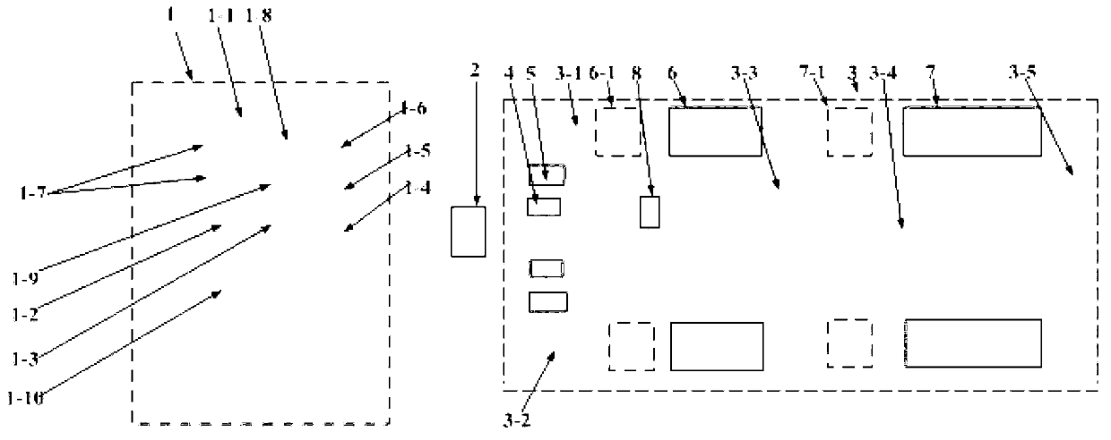
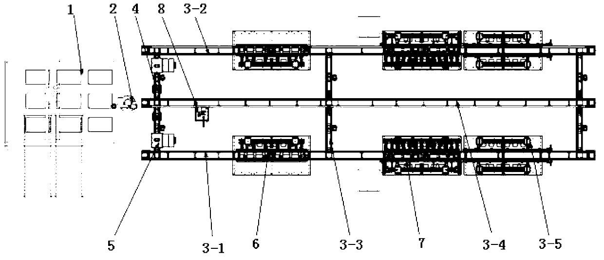
[0092] Such as figure 1As shown, it is a structural block diagram of the present invention. The low-voltage current transformer automatic verification system includes a warehouse-in and outbound connection station module 1 and a matt frame-shaped conveying line 3. The loading and unloading robot 2 adopts a multi-degree-of-freedom loading and unloading robot 2 to realize waiting Verify the feeding of transformers from the input and output connection station module 1 to the grid-shaped frame-shaped conveying line 3, and the verification of the transformer from the grid-shaped frame-shaped conveying line 3 to the input and output connection station module 1 cutting.

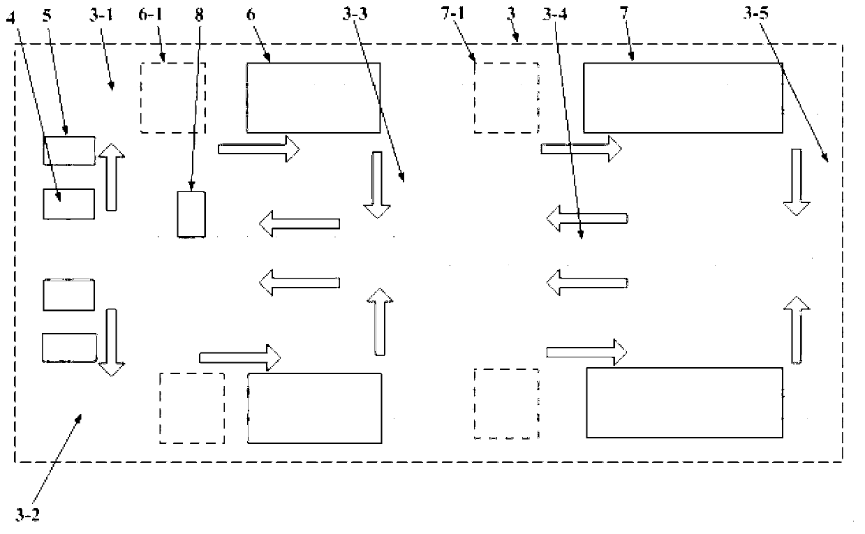
[0093] The above-mentioned matt frame-shaped conveying line 3 includes a main verification conveying line 3-1 with a symmetrical upper and lower structure and a spare verification conveying line 3-2, and the verification conveying line is sequentially provided with a loading and unloading station module 4 and an app...


PUM


Abstract

The invention relates to an automatic verification system of a low-voltage current transformer in power industries. The automatic verification system comprises an input-output warehouse connection station, a grid-shaped frame type conveyor line and a feeding and blanking rotor which is connected with the input-output warehouse connection station and the grid-shaped frame type conveyor line, wherein the grid-shaped frame type conveyor line comprises a main verification conveyor line and a reserved verification conveyor line with up and down symmetrical structures, feeding and blanking station modules, appearance inspection station modules, insulation voltage-withstanding testing station modules and error verification station modules are sequentially arranged on the verification conveyor lines, middle return conveyor lines perpendicular to the verification conveyor lines are arranged between the insulation voltage-withstanding testing station modules and the error verification station modules, terminal return conveyor lines are arranged behind the error verification station modules, a conveyor line shared by the main verification conveyor line and the reserved verification conveyor line is a blanking conveyor line, and a labeling sorting station module is arranged at a part, which is close to the feeding and blanking station modules, of the blanking conveyor line; buffer areas are arranged between detection station modules on the verification conveyor lines.

Description

technical field [0001] The invention relates to a test system and method for electric power metering devices, in particular to an automatic test system for low-voltage current transformers in the electric power industry. Background technique [0002] The transformer is a metering device of the power system, and the workload of testing it is usually very heavy. At present, the detection of transformers is artificially assisted, and various measuring equipment can only measure part of the indicators. It has the disadvantages of using a lot of manpower, high investment in equipment, large floor space, and low efficiency. It cannot meet the needs of mass testing, and the testing results will also be affected by human factors. [0003] The State Grid promotes the application of automatic detection lines for transformers. It is required to be able to automatically complete the warehouse entry and exit, automatically complete the verification of appearance, insulation, withstand ...

Claims


Application Information

Patent Timeline
IPC IPC(8): G01R31/12G01R35/00G01N21/84B65G47/90
Inventor 欧钟高大智牛怀新何雪松冯正奎钟宏斌曹德军乔一坤
Owner 河北海纳电测仪器股份有限公司
Why Eureka
Eureka Blog
Learn More