
Device and method for dual-mode surface plasmon coupled emission fluorescence imaging detection

A surface plasmon and fluorescence imaging technology, which is applied in the direction of fluorescence/phosphorescence, material excitation analysis, etc., can solve the problems of simple function, single imaging device mode, and limit the promotion of SPCE imaging technology, and achieve the effect of reducing costs

Active Publication Date: 2015-10-14
XIAMEN UNIV
View PDF5 Cites 0 Cited by
  • Summary
  • Abstract
  • Description
  • Claims
  • Application Information

AI Technical Summary

Problems solved by technology

However, the above-mentioned RK mode SPCE imaging device based on the prism configuration also has the following disadvantages: the imaging device has a single mode and simple functions. Because its incident light path is fixed and the angle of the incident light cannot be changed, it can only perform RK mode SPCE. imaging
However, in KR mode SPCE imaging detection, only the excitation light incident at the excitation angle of the surface plasmon can induce the surface plasmon to generate an evanescent field, so the angle of the incident light needs to be adjusted; at the same time, the angle difference between the excitation light and its reflected light and the emitted light Smaller, it is necessary to use a high-performance filter to remove the interference of the excitation light or its reflected light. Therefore, in a single mode, whether it is a KR mode or an RK mode SPCE imaging device, it is often encountered in research and application. Big bottlenecks and challenges limit the promotion of SPCE imaging technology

Method used


Image

  • Device and method for dual-mode surface plasmon coupled emission fluorescence imaging detection
  • Device and method for dual-mode surface plasmon coupled emission fluorescence imaging detection
  • Device and method for dual-mode surface plasmon coupled emission fluorescence imaging detection

Examples


Embodiment Construction

[0036] The present invention will be further described below in conjunction with the embodiments and accompanying drawings.

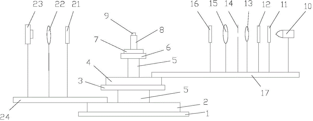
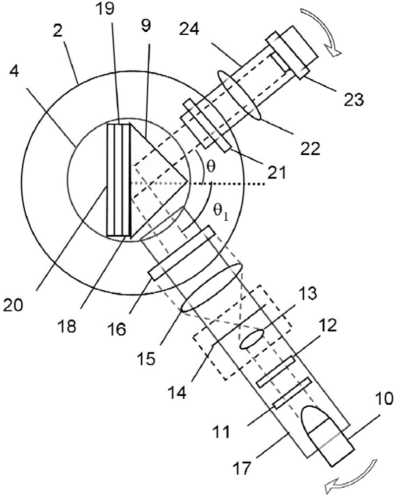
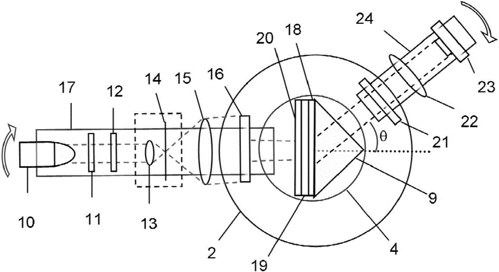
[0037] Such as Figure 1~3 As shown, the dual-mode surface plasmon coupled emission fluorescence imaging detection device in this embodiment is provided with a sample system, an incident arm system and a detection arm system.

[0038] The sample system includes a double rotating stage, a sample holder 8 , a prism 9 and an optical quartz substrate 18 . The double turntable as figure 1 As shown, it is a coaxial structure of the upper and lower layers, including the lower adapter plate 1, the lower rotary table 2, the upper adapter plate 3, the upper rotary table 4 and the central axis 5 of the "convex" structure. The upper turntable 4 is fixed on the central shoulder of the central shaft 5 through the upper adapter plate 3, so as to ensure that the upper and lower turntables are concentric. The lower rotating table 2 is fixed on the external optical pl...


PUM

PropertyMeasurementUnit
diameteraaaaaaaaaa
wavelengthaaaaaaaaaa
thicknessaaaaaaaaaa

Abstract

The invention discloses a dual-mode surface plasmon coupled emission (SPCE) fluorescence imaging detection device and a dual-mode surface plasmon coupled emission fluorescence imaging detection method, and relates to fluorescence imaging detection. The device comprises a sample system, an incident arm system and a detection arm system, wherein the sample system comprises double rotary tables, a sample holder, a prism and an optical quartz substrate; the double rotary tables comprise an upper rotary table, a lower rotary table and a central shaft; the incident arm system comprises a laser source, an attenuator, a polarizer, an microobjective, a pinhole, a planoconvex lens, a square iris diaphragm and a first optical guide rail; the detection arm system comprises a light filter, an imaging lens, a CCD (charge coupled device) receiver and a second optical guide rail. The size of the square iris diaphragm in the incident arm system is adjusted to obtain a rectangular incident light spot with a proper size; the detection of SPCE imaging in an RK (Kretschmann) mode is selected; the detection of SPCE imaging in a KR (Reverse Kretschmann) mode is selected. Therefore, the problem of difficulty for detection when a fluorescence signal is weak in the single RK mode can be effectively avoided.

Description

technical field [0001] The invention relates to a fluorescence imaging detection, in particular to a dual-mode surface plasmon coupled emission fluorescence imaging detection device and detection method. Background technique [0002] Due to its high sensitivity, fluorescence analysis technology has been widely used in the fields of modern biochemical research and disease diagnosis. However, in order to detect analytes at low concentrations or under complex substrates, people are still working on the development of new fluorescence techniques and instruments to further improve the sensitivity of fluorescence. Surface Plasmon Coupled Emission (SPCE) has gradually attracted the interest of researchers due to its unique properties such as fluorescence enhancement, directional emission, high polarization, distance sensitivity, spectral resolution and background suppression. The principle of SPCE is: after the excited state fluorophore in the 200nm range of the smooth nano-metal ...

Claims


Application Information

Patent Timeline
Patent Type & Authority Patents(China)
IPC IPC(8): G01N21/64
Inventor 李耀群蔡伟鹏刘倩曹烁晖谢凯信翁玉华
Owner XIAMEN UNIV
Learn More