
Axial loading system and loading method

An axial loading and axial technology, applied in the direction of applying stable tension/pressure to test the strength of materials, measuring devices, instruments, etc., can solve the problem of loading environment, high installation conditions, self-heavy hydraulic jack, hydraulic loading device Damage and other problems, to achieve the effect of wide application range, long loading stroke and stable load

Inactive Publication Date: 2013-10-09
NORTHEASTERN UNIV
View PDF5 Cites 7 Cited by
  • Summary
  • Abstract
  • Description
  • Claims
  • Application Information

AI Technical Summary

Problems solved by technology

[0004] Among them, the hydraulic jack has a large self-weight, inconvenient on-site installation, small force transmission surface, and uneven force on the test piece; although the hydraulic pillow has large loading capacity, light weight, large force transmission surface and uniform force transmission, the stroke is very small, generally only 4mm, high requirements for loading environment and installation conditions, and cannot be reused
[0005] The above loading methods all use a hydraulic device to achieve loading. Since the hydraulic device has the characteristics of high cylinder sealing requirements and high manufacturing costs, if the test piece is subjected to a test with shock and vibration characteristics such as blasting after the test piece is loaded, the blasting will occur. Vibrations and shocks may cause damage to the hydraulic loading device

Method used


Image

  • Axial loading system and loading method
  • Axial loading system and loading method

Examples


Embodiment Construction

[0029] The present invention will be further described in detail below in conjunction with the accompanying drawings and specific embodiments.

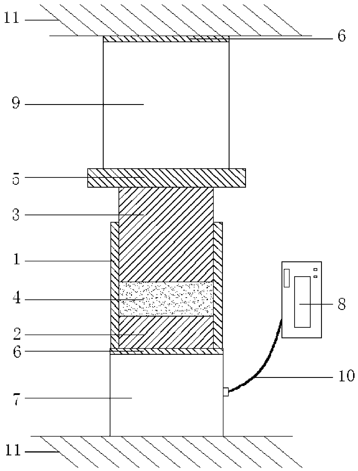
[0030] Such as figure 1 As shown, an axial loading system includes a loading device part and a load measuring part, and the loading device part includes a tube 1, a first piston 2, a second piston 3, an expansion agent 4 and a rigid frame body 11; The load measuring part described above includes a pressure sensor 7, a static strain gauge 8 and a cable 10;

[0031] The tube 1 has a through hole, and the first piston 2 and the second piston 3 are arranged in the through hole of the tube 1. The radial dimensions of the first piston 2 and the second piston 3 are the same. An expansion agent 4 is arranged between the second pistons 3; both the first piston 2 and the second piston 3 are in clearance fit with the tube tube 1; the tube tube 1 is arranged between the loaded body 9 and the pressure sensor 7, so The second piston 3 is in conta...


PUM

PropertyMeasurementUnit
thicknessaaaaaaaaaa
diameteraaaaaaaaaa

Abstract

The invention provides an axial loading system and a loading method and belongs to the technical field of geotechnical engineering. A first piston and a second piston are arranged in a pipe barrel, a swelling agent is arranged between the first piston and the second piston, the pipe barrel is arranged between a loaded body and a pressure sensor, the second piston is in contact with the loaded body, the loaded body is in contact with a rigid frame body, the first piston is in contact with the pressure sensor, and the pressure sensor is in contact with the rigid frame body. The loading method comprises the following steps that: the pressure sensor is arranged on the rigid frame body; the first piston is arranged in the bottom of the pipe barrel, and the pipe barrel is arranged on the pressure sensor; the swelling agent is filled into the pipe barrel, and a plastic film covers the swelling agent after the swelling agent is tamped to be smooth; the second piston is put in the pipe barrel, and the loaded body is arranged on the upper surface of the second piston; along with the swelling of the volume of the swelling agent, the swelling agent can axially push the first piston and the second piston, and the pressure sensor can be used for recording a value of swelling pressure applied to the loaded body and transferring the value to a statical strain indicator.

Description

technical field [0001] The invention belongs to the technical field of geotechnical engineering, in particular to an axial loading system and a loading method. Background technique [0002] In the field of geotechnical engineering, the most commonly used method for the study of the physical and mechanical properties of rocks is to collect rock samples from the site, process them into standard size test pieces in the laboratory, and use a pressure testing machine to perform uniaxial and biaxial tests on them. , Conventional triaxial or true triaxial loading test to obtain relevant rock mechanical performance parameters. [0003] Since the pressure testing machine can only be installed indoors, in order to reflect the anisotropy of the rock mass and make the tested body contain more natural structural surfaces, the test is usually carried out by in-situ loading of a large rock mass, and hydraulic pressure is often used in the test. Jacks and hydraulic pillows load the rock ma...

Claims


Application Information

Patent Timeline
Patent Type & Authority Applications(China)
IPC IPC(8): G01N3/02G01N3/12
Inventor 张凤鹏戴星航李元辉冯夏庭邱兆国田军刘建坡
Owner NORTHEASTERN UNIV
Learn More