
Tool bit of glass cutter

A cutting machine and cutter head technology, applied in glass cutting devices, glass manufacturing equipment, manufacturing tools, etc., can solve the problems of easily damaged cutter heads, easily damaged cutter grains, and insufficient flexibility, and achieve the effect of simple structure

Active Publication Date: 2013-10-09
GUILIN UNIV OF ELECTRONIC TECH
View PDF4 Cites 9 Cited by
  • Summary
  • Abstract
  • Description
  • Claims
  • Application Information

AI Technical Summary

Problems solved by technology

[0002] Although the cutter head equipped on the existing glass cutting machine on the market can also rotate 360°, it is not flexible enough. When the cutter grain rotates, there is a certain amount of friction between the knife grain and the front connection of the knife, which is easy to wear after long-term use. The connection between the knife grain and the front of the knife affects the accuracy of later use; the existing knife head cannot adjust the amount of kerosene dripping with the speed of the knife head movement. When the speed is fast, the dripping oil cannot follow the speed of the knife head movement. Changing and changing is not conducive to the cracking of the glass later, and when the cutter head leaves the glass and then moves to a place with glass, it is easy to damage the cutter head, and it is impossible to detect whether the blade leaves the glass, and it is easy to damage the blade blade

Method used


Image

  • Tool bit of glass cutter
  • Tool bit of glass cutter

Examples


Embodiment Construction

[0016] The content of the present invention will be further described below in conjunction with the accompanying drawings and embodiments, but the present invention is not limited thereto.

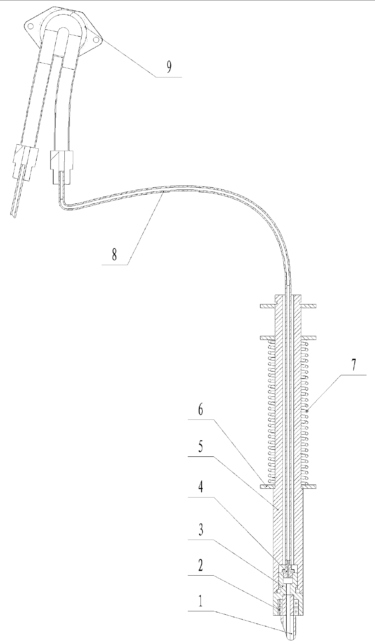
[0017] refer to figure 1 , a cutter head of a glass cutting machine, comprising a knife grain 1, a knife head connection 3, a knife rod 5, an oil delivery pipe 8, and an oil pipe joint 4, the knife head connection 3 is arranged on the front end of the knife rod 5, and the knife grain 1 is arranged on the knife head connection 3, the oil pipe joint 4 is arranged above the knife grain 1 in the cutter bar 5, communicates with the oil delivery pipe 8, and also includes

[0018] Bearing 2, knife grain 1 is rotatably connected with the front head of the knife through bearing 2; bearing 2 is two, and the two bearings are stacked up and down to ensure that knife grain 1 can rotate 360° flexibly; bearing 2 is a model of The 624Z bearing has an outer diameter of 13mm and an inner diameter of 5mm. T...


PUM


Abstract

The invention discloses a tool bit of a glass cutter. The tool bit of the glass cutter comprises a tool grain, a tool front head link, a tool bar, an oil conveying pipe, an oil pipe joint as well as a tool bit control circuit, wherein the tool front head link is arranged on the front end of the tool bar; the tool grain is arranged on the tool front head link; and the oil pipe joint is arranged above the tool grain in the tool bar, and is communicated with the oil conveying pipe. The tool bit of the glass cutter is characterized by also comprising a bearing and a peristaltic pump, wherein the tool grain and the tool front head link are rotatably connected through the bearing; a pump pipe of the peristaltic pump is communicated with the oil conveying pipe; a driver of the peristaltic pump is connected with the tool bit control circuit; the tool bit of the glass cutter is also provided with a tool bit protection device comprising a photoelectric sensor and a distance sensor which are arranged on a steering engine; the steering engine, the photoelectric sensor and the distance sensor are connected with a sensor servo control circuit; the sensor servo control circuit is connected with the tool bit control circuit; and the steering engine is arranged on the tool bar. The tool bit disclosed by the invention has the advantages that the tool grain rotates flexibly; glass after being cut is even to crack; and the tool grain is difficult to be damaged.

Description

technical field [0001] The invention relates to a glass processing machine, in particular to a glass cutter head. Background technique [0002] Although the cutter head equipped on the existing glass cutting machine on the market can also rotate 360°, it is not flexible enough. When the cutter grain rotates, there is a certain amount of friction between the knife grain and the front connection of the knife, which is easy to wear after long-term use. The connection between the knife grain and the front of the knife affects the accuracy of later use; the existing knife head cannot adjust the amount of kerosene dripping with the speed of the knife head movement. When the speed is fast, the dripping oil cannot follow the speed of the knife head movement. Changing and changing is not conducive to the cracking of the subsequent glass, and when the cutter head leaves the glass and then moves to a place with glass, it is easy to damage the cutter head, and it is impossible to detect...

Claims


Application Information

Patent Timeline
IPC IPC(8): C03B33/00
Inventor 唐亮郭勇徐晋勇罗奕张应红赵龙阳高波严小强
Owner GUILIN UNIV OF ELECTRONIC TECH
Learn More