
Discharging box and drying and classifying equipment

A technology for discharging boxes and equipment, which is applied in the direction of transportation and packaging, containers, packaging, etc., and can solve the problems of shortening the service life of equipment, accumulation of many material layers, and equipment wear and tear

Active Publication Date: 2013-10-09
ZOOMLION HEAVY IND CO LTD
View PDF6 Cites 2 Cited by
  • Summary
  • Abstract
  • Description
  • Claims
  • Application Information

AI Technical Summary

Problems solved by technology

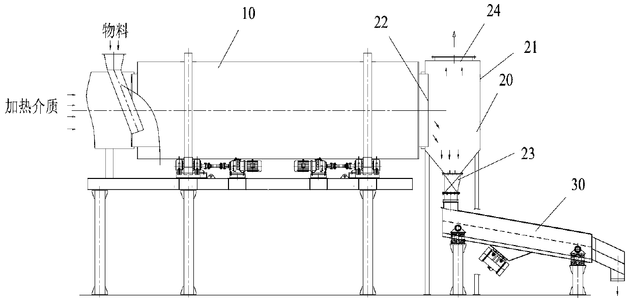
[0003] Among them, the discharge box 20 is only responsible for the storage of materials, including a box body 21 with a material inlet 22, a material outlet 23 and an air outlet 24. After the material enters the box body 21 with the gas, part of the material falls into the material outlet 23 and is discharged. Enter the screening machine 30, but a large amount of fine particle materials are sucked away by the suction device installed at the air outlet 24, which affects the particle gradation of the material and the performance index of the dry-mixed mortar
The fine particle material sucked away will cause the wear of the dust removal pipe and the bag of the dust collector, shortening the service life of the equipment
In addition, more materials enter the entrance of the screening machine 30 from the discharge port, resulting in more accumulation of material layers at the entrance of the screening machine 30, and the screening efficiency and production capacity are limited.
[0004] Therefore, there are the problems of low aggregate efficiency and serious equipment wear in the prior art

Method used


Image

  • Discharging box and drying and classifying equipment
  • Discharging box and drying and classifying equipment
  • Discharging box and drying and classifying equipment

Examples


Embodiment Construction

[0023] Specific embodiments of the present invention will be described in detail below in conjunction with the accompanying drawings. It should be understood that the specific embodiments described here are only used to illustrate and explain the present invention, and are not intended to limit the present invention.

[0024] In the present invention, in the case of no contrary description, the used orientation words such as "up, down, left and right" usually refer to the up, down, left and right shown in the accompanying drawings; "inside and outside" Refers to the inside and outside of the outline of each part itself.

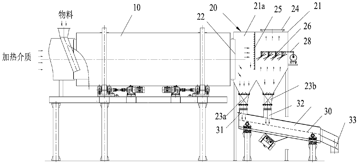
[0025] According to one aspect of the present invention, a discharge box is provided, wherein the discharge box 20 includes a box body 21 and a first baffle plate 25 and a second material baffle plate 26 arranged in the box body 21, so The discharge box 20 has a material inlet 22, a material outlet 23 and an air outlet 24 that communicate with each other. T...


PUM


Abstract

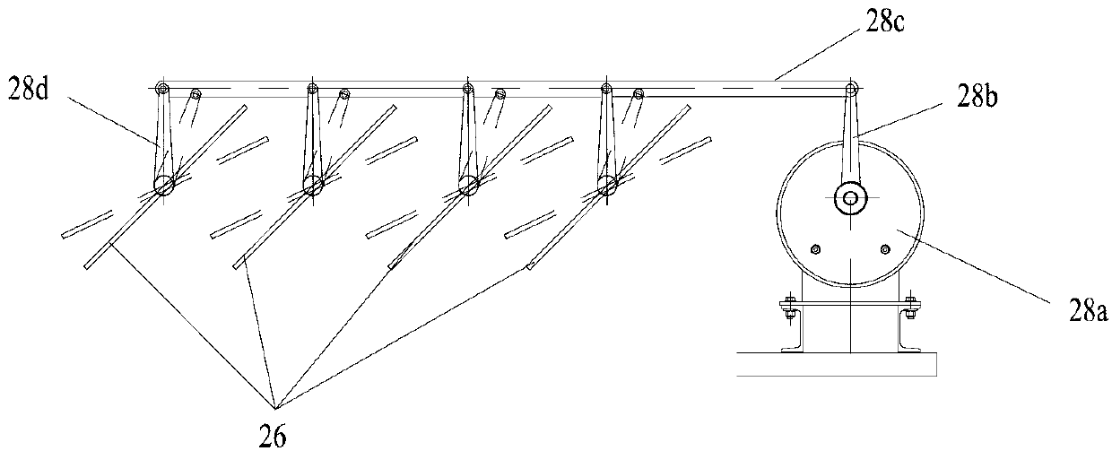
The invention discloses a discharging box and a set of drying and classifying equipment comprising the discharging box. The discharging box (20) comprises a box body (21), a first material stop plate (25) and a second material stop plate (26), wherein the first material stop plate (25) and the second material stop plate (26) are arranged in the box body. A feed port (22), a discharge port (23) and an air outlet (24) are formed in the discharging box and are mutually communicated. The feed port is horizontally arranged, and the discharge port and the air outlet are formed in the bottom and the top of the box body respectively. The first material stop plate is arranged toward the feed port, and the second material stop plate is arranged below the air outlet. Most fine-particle material in material entering the discharging box can be separated from an air stream through collision with the first material stop plate and thus can fall into the discharge port through self weight; a small amount of fine-particle material will flow toward the air outlet under the pumping action of a pumping device and be separated from the air stream through collision with the second material stop plate, and thus can also fall into the discharge port through self weight. Therefore, the discharging box can promote material collecting efficiency and reduce equipment abrasion.

Description

technical field [0001] The invention relates to drying and grading of materials, in particular to a discharge box and drying and grading equipment including the discharge box. Background technique [0002] When the material is used, it is sometimes necessary to dry and classify the material. For example, dry-mixed mortar equipment uniformly premixes dried sand with cement, mineral powder, additives, etc. to form dry-mixed mortar (or dry powder mortar). Before premixing, the materials need to be dried and graded, such as figure 1 This is mainly done by drying drum 10 , discharge box 20 and screen 30 as shown. Among them, the wet material enters the drying drum 10 from one end, and under the action of the heating medium, the material is gradually dried during the forward movement, and then enters the discharge box 20 and the screening machine 30 in turn, so that the over-specified material is removed, and the qualified material It is sent to the dry-mixed mortar production ...

Claims


Application Information

Patent Timeline
IPC IPC(8): B65D90/00
Inventor 尹友中
Owner ZOOMLION HEAVY IND CO LTD
Learn More