A tbm cutter head motor inertia flywheel compound driving device

An inertial flywheel and driving device technology, applied in mining equipment, earthwork drilling, tunnels, etc., can solve the problems of affecting the driving speed, poor drive characteristics of variable frequency motors, and poor geological adaptability, etc., and achieve reduced hydraulic installed power and instantaneous escape torque The effect of large and low installed power

Active Publication Date: 2016-07-06
ZHEJIANG UNIV
View PDF6 Cites 0 Cited by
  • Summary
  • Abstract
  • Description
  • Claims
  • Application Information

AI Technical Summary

Problems solved by technology

[0004] The main problems of the two-speed motor main drive + hydraulic motor auxiliary drive are: (1) The speed cannot be adjusted continuously, and the geological adaptability is poor; (2) The transmission mechanism is complicated, and the failure rate is high, which affects the excavation speed; (3) The hydraulic motor and The motors cannot be driven simultaneously
[0005] Frequency conversion motor drive is the main drive mode at present. Although the frequency conversion motor can output larger torque at low speed than ordinary motors, due to the limitation of the maximum electromagnetic torque, the release torque of the frequency conversion motor drive is limited.
At the beginning of the start, the drive characteristics of the variable frequency motor are very poor, so getting out of trouble is still a technical problem that needs to be solved in the TBM industry

Method used


Image

  • A tbm cutter head motor inertia flywheel compound driving device

Examples


Embodiment Construction

[0015] The present invention will be further described below in conjunction with the accompanying drawings and specific embodiments.

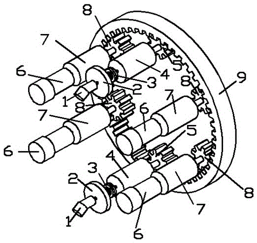
[0016] Such as figure 1 As shown, the TBM cutterhead motor-hydraulic-motor composite driving device of the present invention includes a large ring gear 9, a variable frequency motor driving mechanism and an inertial flywheel driving mechanism.

[0017] Wherein, the variable frequency motor drive mechanism includes a variable frequency motor 6 , a first speed reducer 7 and a first pinion 8 . The output shaft of the frequency conversion motor 6 is connected with the input shaft of the first reducer 7 , the output shaft of the first reducer 7 is fixedly connected with the first pinion 8 , and the first pinion 8 meshes with the large ring gear 9 .

[0018] The inertial flywheel driving mechanism mainly includes an inertial flywheel 2 , a viscous clutch 3 , a second speed reducer 4 , a second pinion 5 and a hydraulic motor 1 . The output shaft of ...


PUM


Abstract

The invention discloses a cutterhead motor and inertia flywheel compound driving device of a TBM (Tunnel Boring Machine), which comprises a large gear ring, a variable-frequency motor driving mechanism and an inertia flywheel driving mechanism, wherein the variable-frequency motor driving mechanism comprises first pinions, first speed reducers, variable-frequency motors and hydraulic motors; the first pinions are engaged with the large gear ring; output shafts of the first speed reducers are fixedly connected with the first pinions; input shafts of the first speed reducers are connected with output shafts of the variable-frequency motors; the inertia flywheel driving mechanism comprises second pinions, second speed reducers, wet clutches and inertia flywheels; the second pinions are engaged with the large gear ring; output shafts of the second speed reducers are fixedly connected with the second pinions; input shafts of the second speed reducers are connected with output shafts of the wet clutches; input shafts of the wet clutches are connected with output shafts of the inertia flywheels; and input shafts of the inertia flywheels are connected with output shafts of the hydraulic motors. The device has the advantages that required power is low, and an instantaneous breakout torque is large.

Description

technical field [0001] The invention relates to a technique for obtaining and controlling instantaneous large torque, in particular to a technique for getting out of trouble of a full-face rock tunnel boring machine cutterhead. Background technique [0002] The cutter head drive system is the core component of the TBM (full-face tunnel boring machine), which is mainly composed of multiple drive motors or hydraulic motors, planetary gear reducers, pinion and large ring gears, main bearings, and a sealed cooling system. At present, the driving methods of TBM mainly include motor drive and hydraulic drive, and the motor drive includes two-speed motor drive and variable frequency motor drive. The driving power of the TBM cutter head is very large, and the driving efficiency of the hydraulic motor is low. If a single hydraulic motor is used for driving, the power loss is very large and the heat is serious. Therefore, the hydraulic motor drive only exists as an auxiliary driving m...

Claims


Application Information

Patent Timeline
Patent Type & Authority Patents(China)
IPC IPC(8): E21D9/093
Inventor 谢海波洪啸赵阳庄莉杨华勇
Owner ZHEJIANG UNIV
Why Eureka
Try Eureka