
Method and well pattern structure for mining oil deposit with nano magnetofluid displacement

A nano-magnetic fluid and displacement well group technology, which is applied in the direction of production fluid, earthwork drilling, wellbore/well components, etc., can solve the problems of low oil and gas, effective production, high viscosity, etc.

Active Publication Date: 2013-10-02
PETROCHINA CO LTD
View PDF6 Cites 20 Cited by
  • Summary
  • Abstract
  • Description
  • Claims
  • Application Information

AI Technical Summary

Problems solved by technology

[0003] Thin oil reservoirs are usually developed by water flooding. According to incomplete statistics, by the end of 2012, my country's thin oil reservoirs generally entered the period of high water cut and ultra-high water cut, and the comprehensive water cut generally reached more than 85%, but the average recovery degree was less than 40%, the water flooding high-permeability channel formed by water flooding for many years has limited effect on further improving water flooding recovery
[0004] Heavy oil reservoirs are usually developed by steam injection huff and puff or steam flooding. Steam huff and puff has the advantages of small periodic steam injection, long simultaneous production period, high periodic oil-steam ratio, and good economic benefits. However, during steam huff and puff development, due to the underground The viscosity of crude oil is high, and the steam injected into the oil layer is greatly resisted by the high-viscosity crude oil, making it difficult for the steam to enter the deep part of the oil layer to heat a wide range of oil layers. Production, steam huff and puff recovery is low, usually less than 20%
Steam flooding technology is usually used as a successor technology after steam huff and puff, but domestic and foreign steam flooding mine field tests show that due to serious steam channeling during steam injection, the effective production degree is low, the oil-steam ratio is low, and the economic benefits are poor

Method used


Image

  • Method and well pattern structure for mining oil deposit with nano magnetofluid displacement
  • Method and well pattern structure for mining oil deposit with nano magnetofluid displacement

Examples


Embodiment 1

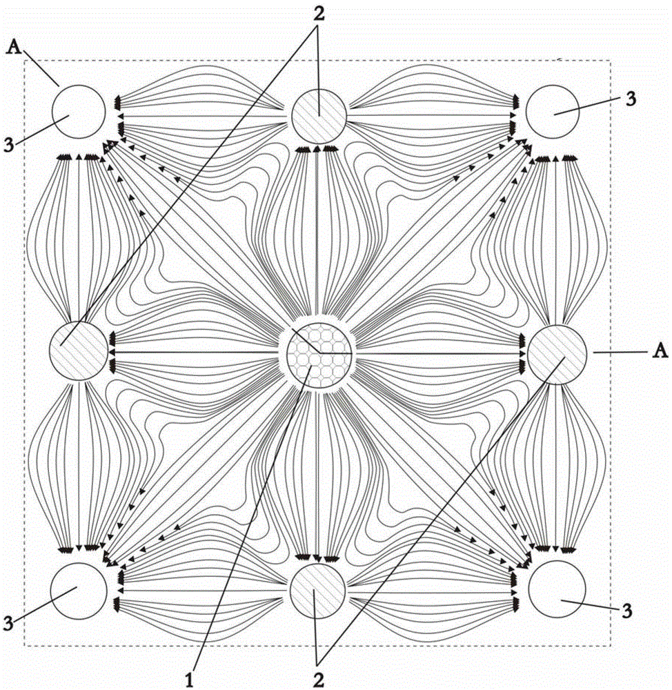
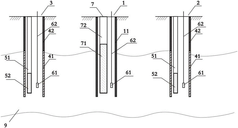
[0048] This embodiment provides a method for nano-magnetic fluid displacement to recover oil reservoirs. Under the conditions of oil layers, the viscosity of degassed crude oil in this oil reservoir is 10 centipoise, and the effective permeability is 15mD. It belongs to conventional low-permeability thin oil reservoirs. The target The effective thickness of the oil layer 9 is 20m, and the target oil layer refers to a certain independent oil layer developed in this embodiment or several independent oil layers developed in general when the oil field production area contains one or several independent oil layers; Water rock, the oil reservoir is now exploited by nano-magnetic fluid displacement.

[0049] step one:

[0050] A well pattern is set in the reservoir area; the well pattern includes at least one displacement well group 100; as figure 1 As shown, the displacement well group 100 includes an injection well 1, and on a square centered on the injection well 1, four side wel...

Embodiment 2

[0068] The principle of this embodiment is basically the same as that of Embodiment 1. The difference is that the viscosity of the degassed crude oil of the heavy oil in the selected reservoir is 1000 centipoise under the conditions of the oil reservoir, which belongs to the heavy oil reservoir. The effective thickness of the target oil layer 9 is 30 m. The rock is oil-loving rock; the oil reservoir is exploited by nano-magnetic fluid flooding.

[0069] step one:

[0070] A well pattern is set in the reservoir area; the well pattern includes at least one displacement well group 100; as figure 1 As shown, the displacement well group 100 includes an injection well 1, and on a square centered on the injection well 1, four side wells 2 and four corner wells 3 are set, and the side wells 2 and corner wells 3 are for production Well, a square anti-nine-point displacement well group is formed by the above-mentioned injection well 1, side well 2 and corner well 3;

[0071]The above-...


PUM

PropertyMeasurementUnit
Particle sizeaaaaaaaaaa
Viscosityaaaaaaaaaa
Particle sizeaaaaaaaaaa

Abstract

The invention discloses a method and a well pattern structure for mining an oil deposit with nano magnetofluid displacement. The method comprises the steps that an injection well, four edge wells and four corner wells form a square inverted nine-spot displacement well group; electromagnets are put into shafts of the edge wells and the corner wells; a nano magnetofluid dispersion solution is injected into the injection well; the electromagnets under the edge wells are started; a magnetic flux is adjusted; the electromagnets under the edge wells are closed; oil flow production is started; the electromagnets under the corner wells are started; a magnetic flux is adjusted; the electromagnets under the corner wells are closed; the oil flow production is started; the electromagnets under the edge wells are started; the magnetic flux is adjusted; and the edge wells and the corner wells alternately apply an electromagnetic field and alternately conduct the oil flow production for a certain period according to the sequence. The method for mining the oil deposit with the nano magnetofluid displacement changes an oil displacement direction and a speed of a nano magnetofluid in an oil layer by adopting the alternate magnetic field and an alternate production mode of the corner wells and the edge wells, so that crude oil between injection and production wells is used effectively, the sweep efficiency of an injection medium is improved, and a recovery ratio of the crude oil in the oil deposit is increased.

Description

technical field [0001] The invention relates to a mining method for thin oil and heavy oil reservoirs in the field of petroleum exploitation, in particular to a method for exploiting reservoirs by nanometer magnetic fluid displacement and its well pattern structure. Background technique [0002] According to the classification standard of crude oil viscosity, oil reservoirs worldwide can be divided into two categories, namely, thin oil reservoirs and heavy oil reservoirs. Among them, heavy oil reservoirs refer to the viscosity of degassed crude oil greater than 100 centimeters under reservoir conditions. Reservoirs above the mooring level, and the rest are thin oil reservoirs. [0003] Thin oil reservoirs are usually developed by water flooding. According to incomplete statistics, by the end of 2012, my country's thin oil reservoirs generally entered the period of high water cut and ultra-high water cut, and the comprehensive water cut generally reached more than 85%, but th...

Claims


Application Information

Patent Timeline
IPC IPC(8): E21B43/16E21B43/30
Inventor 吴永彬王红庄
Owner PETROCHINA CO LTD
Learn More