Partition for coating chamber

A technology for coating chambers and partitions, applied in the field of partitions for coating chambers, can solve the problems of flexible substrates being heated and curled, low-quality flexible functional films, etc., and achieve the effect of reducing heat

Inactive Publication Date: 2016-05-25
NANCHANG O FILM TECH CO LTD +2
View PDF5 Cites 0 Cited by
  • Summary
  • Abstract
  • Description
  • Claims
  • Application Information

AI Technical Summary

Problems solved by technology

As the coating process continues, the temperature at both ends of the separator continues to rise. At the same time, due to the single-layer metal structure at both ends of the traditional separator, heat is easily conducted to the flexible substrate that is close to or attached to the separator, resulting in Flexible substrates are heated and curled, resulting in lower quality flexible functional films

Method used


Image

  • Partition for coating chamber
  • Partition for coating chamber
  • Partition for coating chamber

Examples


Embodiment Construction

[0020] The separator for the coating cavity will be further described below with reference to the accompanying drawings.

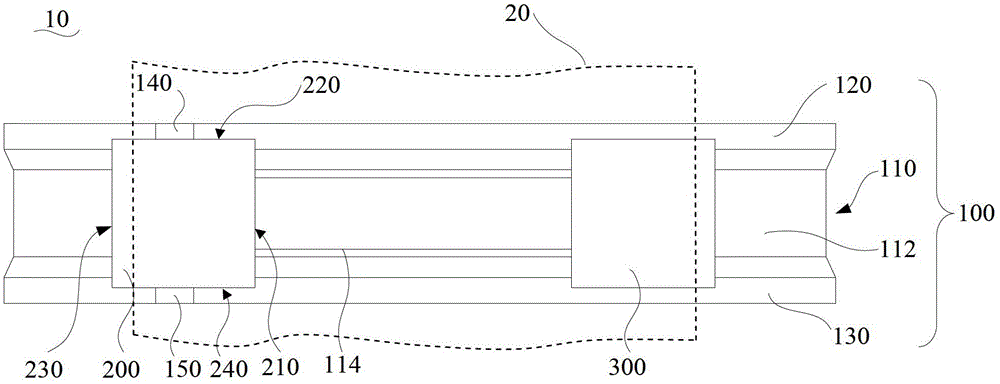
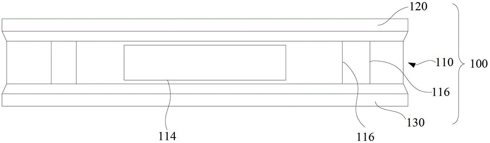
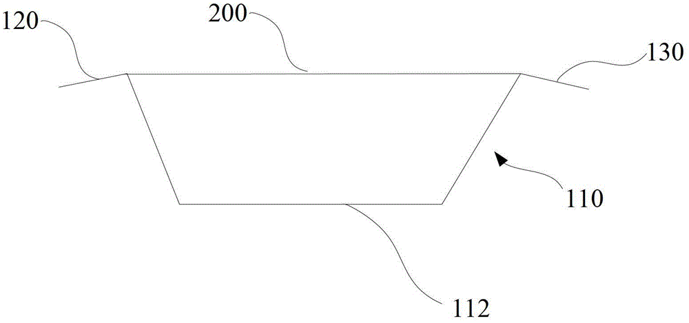
[0021] like figure 1 and figure 2 As shown, the separator 10 for a coating cavity in an embodiment includes a main body 100, a first baffle 200 and a second baffle 300, wherein the main body 100 includes a U-shaped groove plate 110, a first folding edge 120 and a second folding Side 130.

[0022] The U-shaped grooved plate 110 includes a groove bottom 112 and two side walls. A window 114 extending through the groove bottom 112 is provided in the middle of the groove bottom 112 . In this embodiment, the window 114 is rectangular. Under normal circumstances, the length of the window 114 (the direction in which the flexible substrate 20 moves) can be as large as possible under the conditions allowed by the size of the coating chamber, and the width of the window 114 usually needs to be based on the width of the area of ​​the flexible substrate 20 that nee...


PUM


Abstract

The invention relates to a partition plate for a coating chamber, comprising a U-shaped groove plate, a first folded edge, a second folded edge, a first baffle plate and a second baffle plate; the middle part of the groove bottom of the U-shaped groove plate is provided with a through groove The window at the bottom; the first flange and the second flange are respectively connected to the top of the two side walls of the U-shaped groove; the first baffle and the second baffle are both across the U-shaped groove edge and the second edge connection. The partition plate for the coating chamber can effectively reduce the conduction of heat to the flexible base material, and a high-quality flexible functional film can be obtained by applying the partition plate for the coating chamber to coat the film.

Description

technical field [0001] The invention relates to the technical field of coating, in particular to a separator for a coating cavity. Background technique [0002] The roll-to-roll vacuum coating technology is widely used in the production of various flexible functional films, such as the production of ITO transparent conductive films, due to its high production efficiency. [0003] The winding type vacuum coating equipment usually includes a coating roller and several coating chambers arranged around the coating roller. A partition is arranged between the coating roller and the coating chamber. With target. When the flexible substrate is used as the base for coating, one side of the flexible substrate is wound around the coating roller and slides over the coating roller under the action of an external force, while the other side of the flexible substrate is close to or adhered to the separator. During coating, a large number of high-energy particles are generated in the coat...

Claims


Application Information

Patent Timeline
Patent Type & Authority Patents(China)
IPC IPC(8): C23C14/56
Inventor 徐少东
Owner NANCHANG O FILM TECH CO LTD
Why Eureka
Try Eureka