Machining method of T-shaped movable beam irregularly-shaped glass machining system
A special-shaped glass and processing system technology, which is applied to metal processing equipment, machine tools suitable for grinding the edge of workpieces, manufacturing tools, etc. Accidents and other problems, to achieve ideal processing effect, simple and efficient design, and the effect of ensuring personal safety
- Summary
- Abstract
- Description
- Claims
- Application Information
AI Technical Summary
Problems solved by technology
Method used
Image
Examples
Embodiment 1
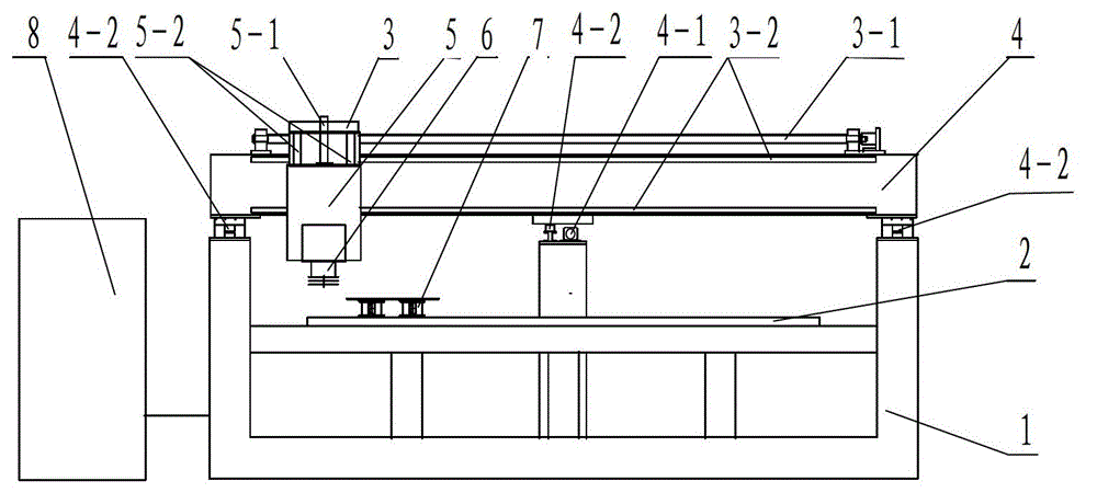
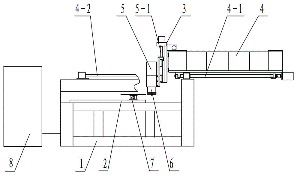
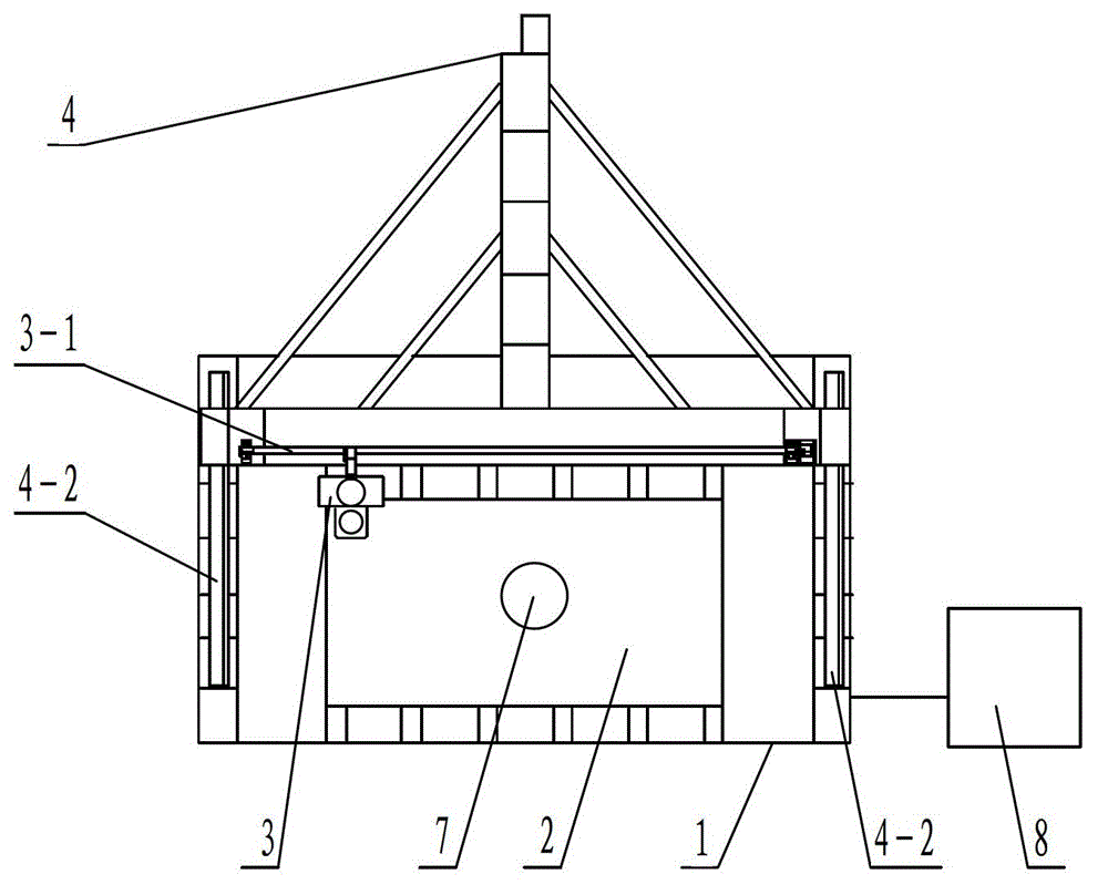
[0029] Put the glass on the positioning suction plate 7 of the fixed platform 2, correct the glass, and vacuum the positioning suction plate 7 by the vacuum pump, so that the upper and lower planes of the positioning suction plate 7 are firmly adsorbed on the glass and the fixed platform 2; the horizontal stepping / servo mechanism 3 The running direction is the X-axis direction, the running direction of the T-shaped longitudinal stepping / servo mechanism 4 along the three Y-axis guide rails 4-2 is the Y-axis direction, and the running direction of the up and down stepping / servo mechanism 5 is the Z-axis direction; the control box 8 According to the set program, the X-axis, Y-axis, and Z-axis are simultaneously linked, and the data control system automatically controls the grinding head mechanism 6 to grind special-shaped glass.
Embodiment 2
[0031] The X-axis screw 3-1 drives the horizontal stepper / servo mechanism 3 to run along the X-axis guide rail 3-2. Click X+ and X- on the computer control interface of the control box 8, and the horizontal stepper / servo mechanism 3 moves along the X axis according to the instruction. The shaft guide rail 3-2 runs to the position to be processed; the Y-axis screw 4-1 under the longitudinal beam of the T-shaped longitudinal stepping / servo mechanism 4 drives the T-shaped longitudinal stepping / servo mechanism 4 along the direction of the three Y-axis guide rails 4-2 Run, click Y+ and Y- on the computer control interface, the T-shaped longitudinal stepping / servo mechanism 4 runs along the three Y-axis guide rails 4-2 to the position to be processed according to the command; the Z-axis screw 5-1 drives the up and down stepping / servo Mechanism 5 and the grinding head mechanism 6 below the up and down stepping / servo mechanism 5 run along the Z-axis guide rail 5-2, click Z+ and Z- on t...
Embodiment 3
[0033] Click X+, X-, Y+, Y-, Z+, Z- on the computer control interface to adjust the grinding head below the grinding head mechanism 6 to be in contact with the edge of the glass to be ground, and control the horizontal stepping / servo mechanism 3 on the computer control interface , T-shaped longitudinal stepping / servo mechanism 4, up and down stepping / servo mechanism 5 running along the X-axis guide rail 3-2, Y-axis guide rail 4-2, and Z-axis guide rail 5-2 respectively, and the three-axis linkage makes the grinding head move along the The edge of the special-shaped glass moves, scans the actual contour of the special-shaped glass, collects the actual contour data of the special-shaped glass, and transmits the data to the computer. After computer calculation, the theoretical contour data of the special-shaped glass is displayed proportionally on the synchronous operation display page. After editing Use the drawing tool on the page to reproduce the theoretical profile of the spec...
PUM
 Abstract
Description
Claims
Application Information
 - R&D
- Intellectual Property
- Life Sciences
- Materials
- Tech Scout
- Unparalleled Data Quality
- Higher Quality Content
- 60% Fewer Hallucinations
Browse by: Latest US Patents, China's latest patents, Technical Efficacy Thesaurus, Application Domain, Technology Topic, Popular Technical Reports.
© 2025 PatSnap. All rights reserved.Legal|Privacy policy|Modern Slavery Act Transparency Statement|Sitemap|About US| Contact US: help@patsnap.com


