
A circuit breaker operating mechanism capable of quick release

A technology of operating mechanism and circuit breaker, applied in the direction of protection switch operation/release mechanism, etc., can solve the problem of increasing the tripping hook, tripping locking device and the tripping force of the opening half-shaft, damaging the transmission parts and shafts of the mechanism, reducing the Mechanical life and other issues, to achieve the effect of reducing tripping time, increasing life, and reducing duration

Active Publication Date: 2015-07-29
JIANGSU DAQO KFINE ELECTRIC
View PDF6 Cites 0 Cited by
  • Summary
  • Abstract
  • Description
  • Claims
  • Application Information

AI Technical Summary

Problems solved by technology

[0002] The traditional operating mechanism of the circuit breaker provides a large mechanical reaction force due to the electric repulsion force, which may damage some transmission parts and shafts of the mechanism, and increase the distance between the trip hook, the trip lock device and the opening half shaft. trip force, reducing mechanical life
And the traditional trip lock device takes about 20ms from receiving the signal to responding, and this tripping time is too long
[0003] Some patents (referring to patent FR-A-2239755, FR-9601661) have proposed some schemes to solve and improve these problems, but all there is the problem of complicated structure, high cost

Method used


Image

  • A circuit breaker operating mechanism capable of quick release
  • A circuit breaker operating mechanism capable of quick release
  • A circuit breaker operating mechanism capable of quick release

Examples


Embodiment Construction

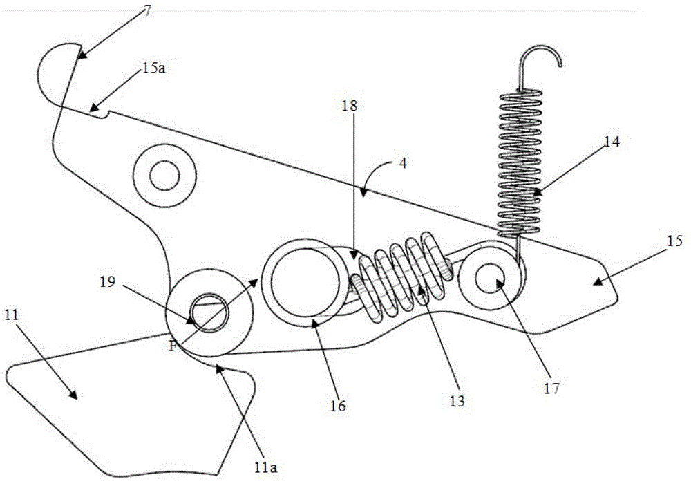
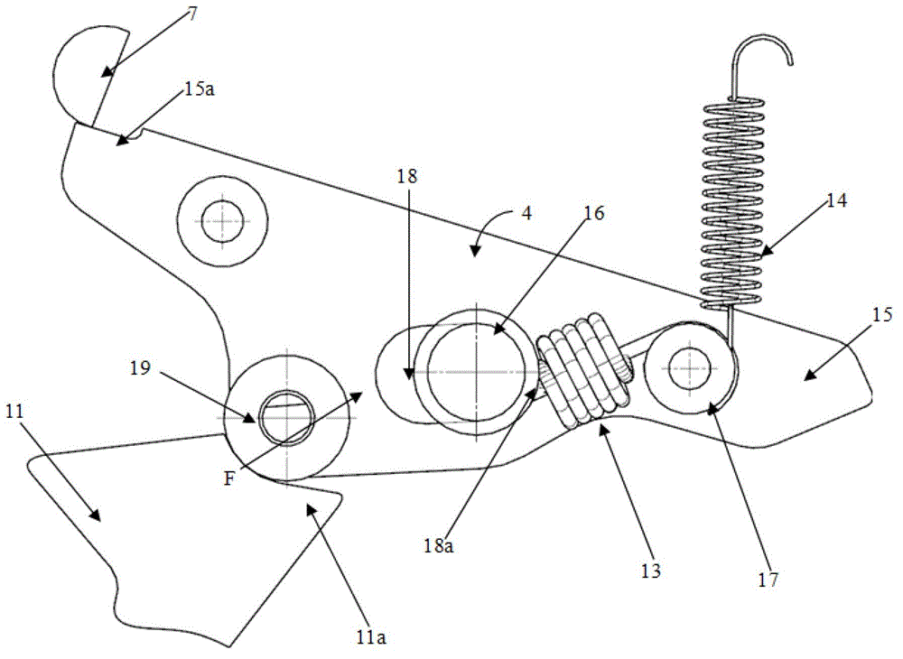
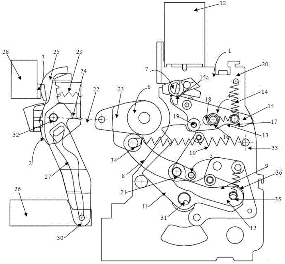
[0014] Its advantages and characteristics will be apparent from the following description of a non-limiting example, taken in conjunction with the accompanying drawings. in:

[0015] The operating mechanism of the present invention includes a power circuit, and each pole has a pair of dynamic and static compensation contacts that are kept closed by the electric compensation effect of repulsion, from figure 1 and figure 2 It can be seen that the operating mechanism 1 of a multi-pole circuit breaker is supported by a frame 20, which includes a tripping linkage device 5, which has transmission rods 8, 9, and the two transmission rods are hinged on the pivot 21, and the transmission rod 8 It is mechanically connected with the switch main shaft 6, and its rotation can realize the closing and breaking of the moving contact 2 and the static contact 3.

[0016] Both ends of the connecting rod 22 are respectively connected to the crank 23 of the switch main shaft 6 and the contact h...


PUM


Abstract

The invention discloses a circuit breaker operating mechanism which is provided with a tripping locking device capable of tripping quickly in a short circuit, wherein the circuit breaker operating mechanism is supported by a rack. The circuit breaker operating mechanism specifically comprises a tripping connecting rod device, a switch spindle, the tripping locking device and a brake separating half shaft. The tripping connecting rod device is related to a tripping hook and a brake separating spring. When the tripping hook moves from a loading position to a brake separating position, a moving contact can be driven to move from an on-position to an off-position. The switch spindle is connected with the tripping connecting rod device and is connected to all moving contacts which support a circuit breaker. The tripping locking device is matched with the tripping hook. When the tripping locking device is at a locking position, the circuit breaker operating mechanism is in a bearing state; when the tripping locking device is at an unlocking position, the circuit breaker operating mechanism is in a jumping state. The brake separating half shaft is controlled by a jumping action piece and used for relieving the locking state of the tripping locking device. When a short-circuit current exceeds a calibrated threshold value, the tripping locking device is at the unlocking position, the circuit breaker operating mechanism trips automatically, and the threshold value is defined by an elastic element. The circuit breaker operating mechanism is simple in structure and easy to realize.

Description

technical field [0001] The invention relates to an operating mechanism of a large electric power low-voltage multi-pole circuit breaker, in particular to an operating mechanism of a circuit breaker with a tripping locking device capable of quick tripping when short-circuited. Background technique [0002] The traditional operating mechanism of the circuit breaker provides a large mechanical reaction force due to the electric repulsion force, which may damage some transmission parts and shafts of the mechanism, and increase the distance between the trip hook, the trip lock device and the opening half shaft. The tripping force reduces the mechanical life. And the traditional trip lock device needs about 20ms from receiving the signal to responding, and this tripping time is too long. [0003] Some patents (referring to patent FR-A-2239755, FR-9601661) have proposed some schemes to solve and improve these problems, but all have the problems of complex structure and high cost. ...

Claims


Application Information

Patent Timeline
Patent Type & Authority Patents(China)
IPC IPC(8): H01H71/12
Inventor 肖威于镇洲王靖
Owner JIANGSU DAQO KFINE ELECTRIC
Learn More