
Device for measuring direct-current resistance and parameters of load switch of transformer

A technology of parameter measurement and transformer, applied in the field of power system, can solve the problems of reducing work efficiency and high purchase cost, and achieve the effect of improving field work efficiency and avoiding different experimental preparations.

Active Publication Date: 2013-09-25
STATE GRID CORP OF CHINA +3
View PDF6 Cites 6 Cited by
  • Summary
  • Abstract
  • Description
  • Claims
  • Application Information

AI Technical Summary

Problems solved by technology

[0003] In the existing test technology, if the above two tests are to be realized, the transformer user needs to configure a dedicated transformer DC resistance tester and a transformer on-load tap-changer parameter tester. Since there are many manufacturers of these two instruments, and there are various types , and the testing method, operation method and wiring method of each manufacturer are different, so if the above two tests are to be carried out, two test preparations and two wiring and disconnection are required, which greatly reduces the work efficiency on site. Moreover, the single purchase cost of the above two instruments is relatively high

Method used


Image

  • Device for measuring direct-current resistance and parameters of load switch of transformer
  • Device for measuring direct-current resistance and parameters of load switch of transformer
  • Device for measuring direct-current resistance and parameters of load switch of transformer

Examples


Embodiment Construction

[0023] The following will clearly and completely describe the technical solutions in the embodiments of the present invention with reference to the accompanying drawings in the embodiments of the present invention. Obviously, the described embodiments are only part of the embodiments of the present invention, not all of them. Based on the embodiments of the present invention, all other embodiments obtained by persons of ordinary skill in the art without creative efforts fall within the protection scope of the present invention.

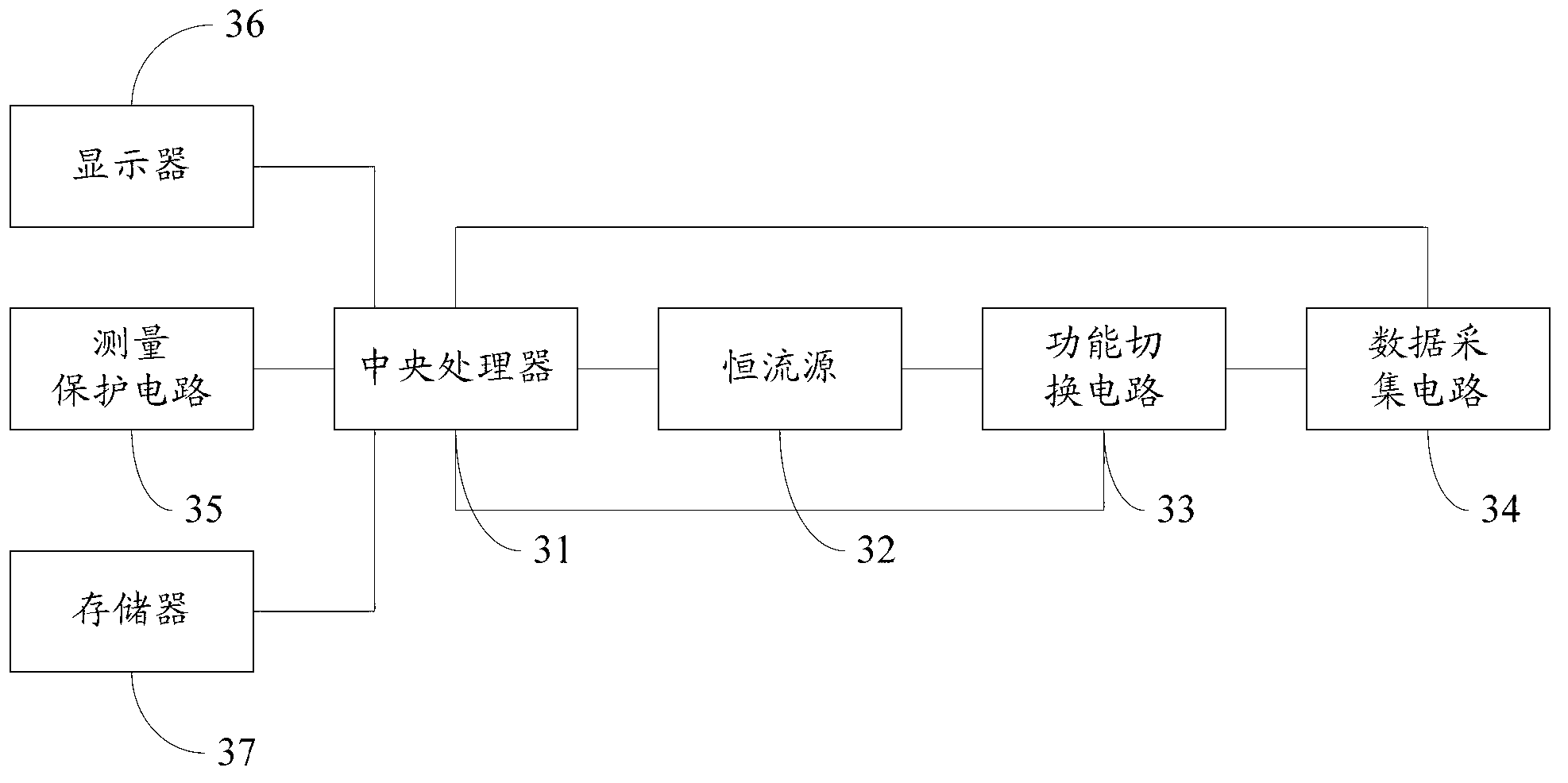
[0024] The embodiment of the invention discloses a transformer direct resistance and on-load switch parameter measuring device, which can simultaneously test the transformer direct resistance and the transformer on-load tap changer parameters.

[0025] Such as figure 1 As shown, it is a transformer direct resistance and on-load switch parameter measuring device disclosed by the present invention, including:

[0026] A central processing unit 11 gener...


PUM


Abstract

The invention discloses a device for measuring direct-current resistance and parameters of a load switch of a transformer. The device for measuring the direct-current resistance and the parameters of the load switch of the transformer comprises a central processing unit, a constant current source, a function switching circuit and a data collecting circuit, wherein the central processing unit is used for generating testing orders, the constant current source is connected with the central processing unit, and outputs constant current signals according to the orders generated by the central processing unit, the function switching circuit is connected with the central processing unit and the constant current source, receives the constant current signals output by the constant current source, and outputs testing signals according to the orders generated by the central processing unit, the data collecting circuit is connected with the function switching circuit, and carries out data collection according to the testing signals output by the function switching circuit, and the central processing unit is further connected with the data collecting circuit, receives data collected by the data collecting circuit, carries out processing on the received data, and outputs measurement results. The device for measuring the direct-current resistance and the parameters of the load switch of the transformer can simultaneously carry out a test of the direct-current resistance of the transformer and a test of the parameters of the load tapping switch of the transformer.

Description

technical field [0001] The invention relates to the technical field of electric power system, and more specifically, relates to a transformer direct resistance and on-load switch parameter measuring device. Background technique [0002] The DC resistance test of the transformer and the parameter test of the on-load tap changer of the transformer are mandatory items for transformer outage maintenance, and are of great significance in each transformer maintenance. [0003] In the existing test technology, if the above two tests are to be realized, the transformer user needs to configure a dedicated transformer DC resistance tester and a transformer on-load tap-changer parameter tester. Since there are many manufacturers of these two instruments, and there are various types , and each manufacturer’s test method, operation method and wiring method are different, so if the above two tests are to be carried out, two test preparations and two wiring and disconnection are required, ...

Claims


Application Information

Patent Timeline
Patent Type & Authority Applications(China)
IPC IPC(8): G01R27/02G01R31/327
Inventor 刘亮泽朱瑾任伟宏吴明袁丹
Owner STATE GRID CORP OF CHINA
Learn More