Ski-jump and jet flow combined energy dissipation device

An energy-dissipating device and jet technology, which can be used in water conservancy projects, sea area projects, coastline protection, etc., and can solve problems such as restrictions on the use of scour pits

Active Publication Date: 2015-05-13
嘉善永升五金厂
View PDF4 Cites 2 Cited by
  • Summary
  • Abstract
  • Description
  • Claims
  • Application Information

AI Technical Summary

Problems solved by technology

Some dams now use scour pits to form water cushions, but this method has many defects: for example, when the anti-scour capacity of the bedrock is not ideal or there are cracks and joints that endanger the safety of the dam body near the formed scour pits, the use of scour pits will be more restricted

Method used


Image

  • Ski-jump and jet flow combined energy dissipation device
  • Ski-jump and jet flow combined energy dissipation device

Examples


Embodiment Construction

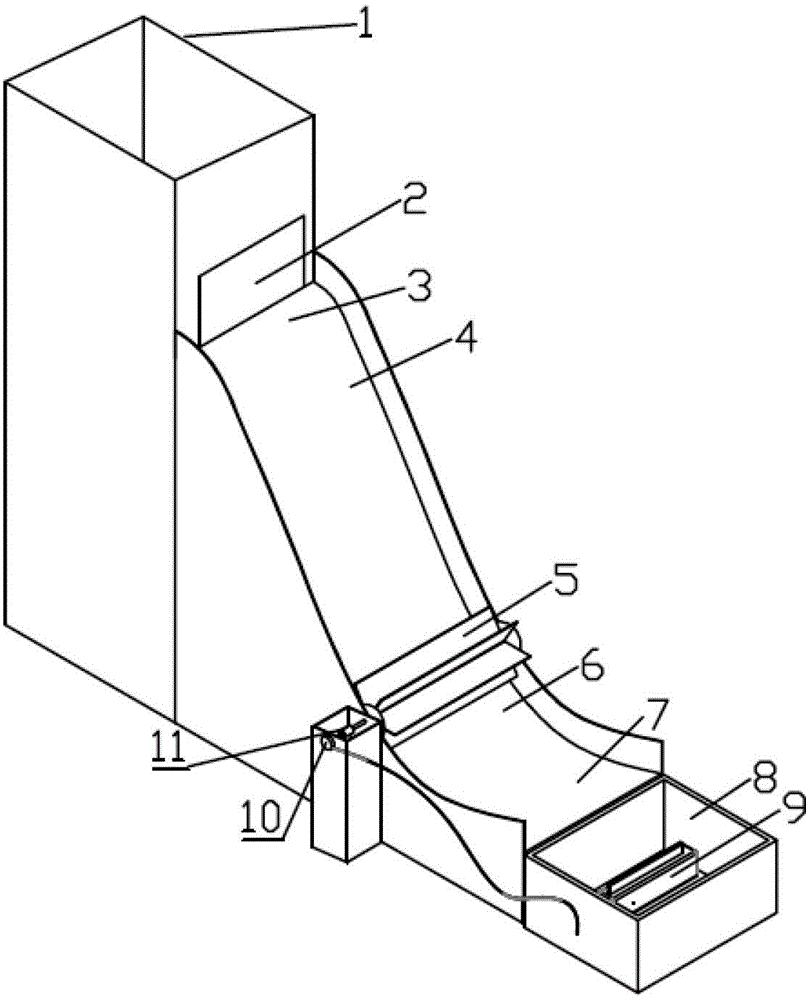
[0012] Such as Figure 1~2 As shown, the combined deflecting flow and jet flow energy dissipation device of the present invention includes a reservoir 1, a dam crest 3, a dam surface 4, an impeller 5, a water cushion pond 8, a high-pressure water pump 9, a generator 10, a bearing, and a shaft coupling And transmission 11 etc. constitute.

[0013] The bottom of the water outlet 2 of the reservoir coincides with the dam crest 3. When the water in the reservoir 1 reaches a certain amount, the water in the reservoir 1 is discharged from the dam crest 3 along the dam surface 4 stably in the form of surface flow. surface flow. The deflection nose sill part of the dam surface is composed of an arc segment 6 with a center angle of 53° and an arc segment 7 with a deflection angle of 25°. Realize the diversion of the water flow and the projecting surface without causing excessive impact on the dam body. The impeller 5 is made up of 5 blades whose length×width is 600mm×105mm, and the ...


PUM


Abstract

The invention discloses a ski-jump and jet flow combined energy dissipation device, and belongs to the technical field of dam flood discharge and energy dissipation. The ski-jump and jet flow combined energy dissipation device is composed of an impounding reservoir, a dam body, a dam surface, an impeller, a generator, a high pressure water pump and a plunge pool. The impounding reservoir, the dam body, the dam surface and the plunge pool are reduced structures of an actual overflow dam. The impeller can be fixed on an appropriate position of the dam surface according to actual requirements. The generator and the impeller are coaxial. The high pressure water pump is arranged inside the plunge pool. High-velocity water flow discharged from a dam top is utilized for impacting the impeller on the overflow dam surface, the impeller rotates to drive the generator to generate electricity and supply power for the high pressure water pump in the plunge pool. The surface-shaped jet flow sprayed upwards from the water pump and the surface-shaped water flow discharged after being flipped by the overflow dam surface collide in the air and dissipate energy. According to the ski-jump and jet flow combined energy dissipation device, a mechanical energy dissipation device is arranged on a ski-jump energy dissipation device for the first time. The ski-jump and jet flow combined energy dissipation device has the advantage of dissipating energy by a sill, nappe convection and the plunge pool, has high energy dissipation and erosion control efficiency and outstanding practical value, and is wide in application prospect.

Description

Technical field: [0001] The invention relates to a deflecting flow and jet flow combined energy dissipation device, which belongs to the technical field of dam flood discharge and energy dissipation, and can realize the purposes of bottom sill energy dissipation, hedging energy dissipation, water cushion pond energy dissipation and ecological energy storage at the same time. Background technique: [0002] In recent years, with the implementation of the country's western development and the strategy of power transmission from west to east, a number of 200-300m high dams will be built in the western alpine and valley areas. These projects generally have the characteristics of high head and large flow of flood discharge, which increases the difficulty of the layout of discharge structures, and there is a contradiction between excessive flood discharge power and small downstream energy dissipation space. In high-head water conservancy and hydropower projects, the problem of high...

Claims


Application Information

Patent Timeline
Patent Type & Authority Patents(China)
IPC IPC(8): E02B8/06
Inventor 戎贵文李琦丁杰吴福贤陈丽周军乔润利
Owner 嘉善永升五金厂
Why Eureka
Try Eureka