Active pay-off device for knitting machine

A technology of a pay-off device and a braiding machine, which is applied in the field of active pay-off devices for braiding machines, and can solve problems affecting the uniformity and compactness of the wire arrangement of the pay-off reel, the inability to install the pay-off reel, and the labor intensity of workers. Achieve the effects of wide application range, saving operation time and reducing labor intensity

Inactive Publication Date: 2013-09-25
SUZHOU CABLEPLUS PHOTOELECTRIC TECH
View PDF10 Cites 1 Cited by
  • Summary
  • Abstract
  • Description
  • Claims
  • Application Information

AI Technical Summary

Problems solved by technology

The disadvantages of the above-mentioned structure are: firstly, a pay-off reel with a large size cannot be installed on the support shaft, so the scope of use is narrow; secondly, the position where the pay-off reel is installed is fixed, and in the actual production process, the pay-off reel cannot be installed. The outer diameter of the reel will often change, which will cause the tension of the semi-finished cable on the pay-off reel to change, and this change in tension will affect the uniformity and compactness of the wire arrangement on the pay-off reel; third, pay-off After the end, the support shaft needs to be removed when replacing the pay-off reel, which is not only labor-intensive and time-consuming, but also very inefficient, and the labor intensity of the workers is also high

Method used


Image

  • Active pay-off device for knitting machine
  • Active pay-off device for knitting machine
  • Active pay-off device for knitting machine

Examples


Embodiment

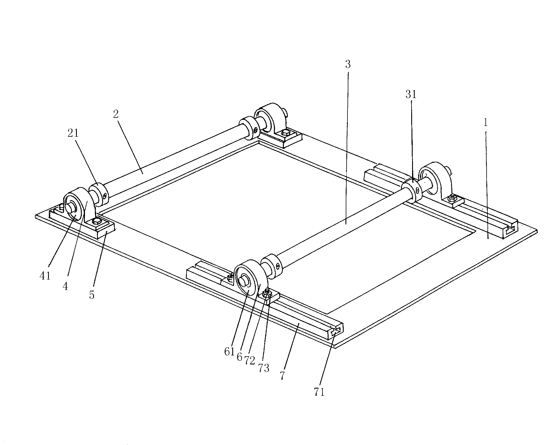
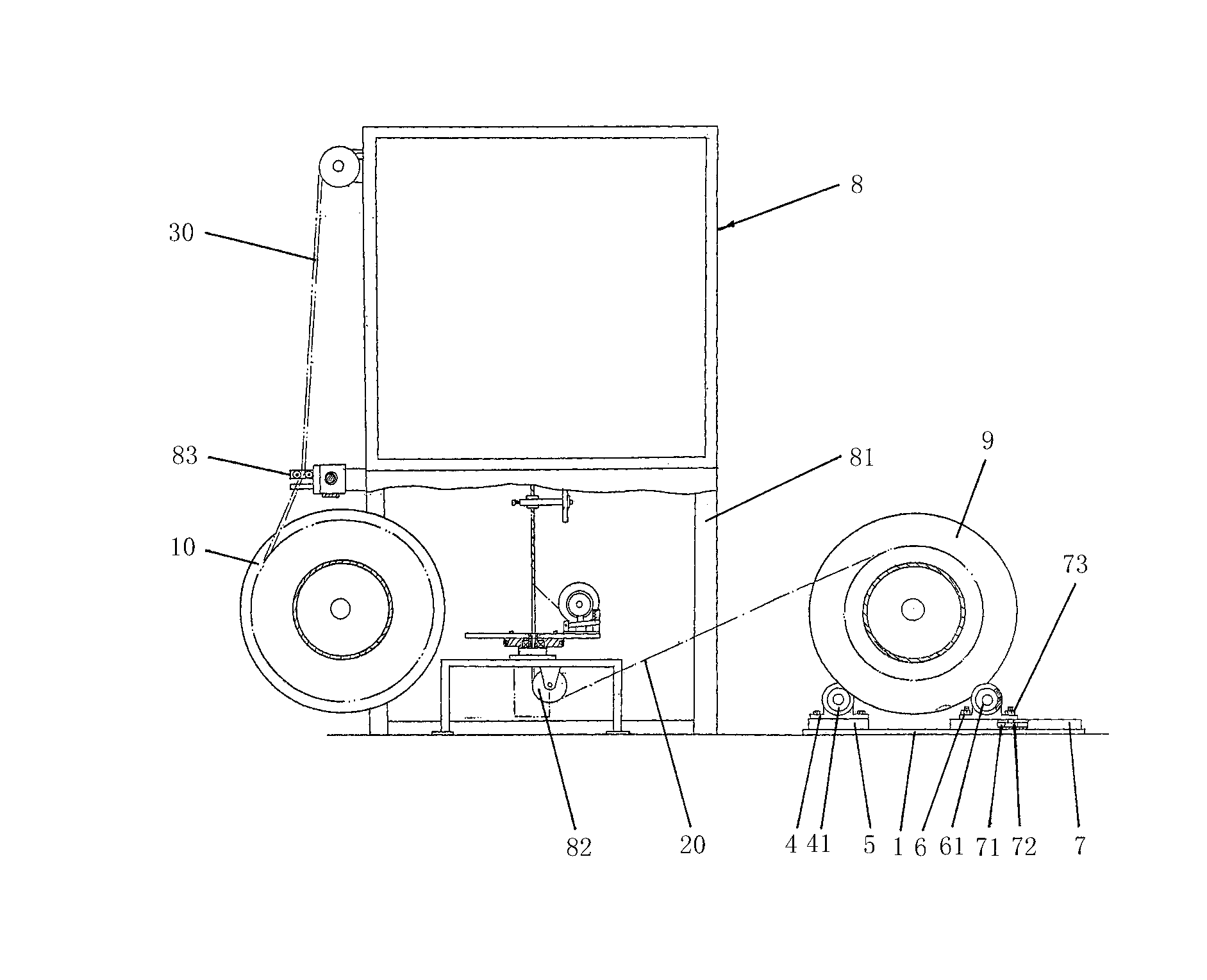
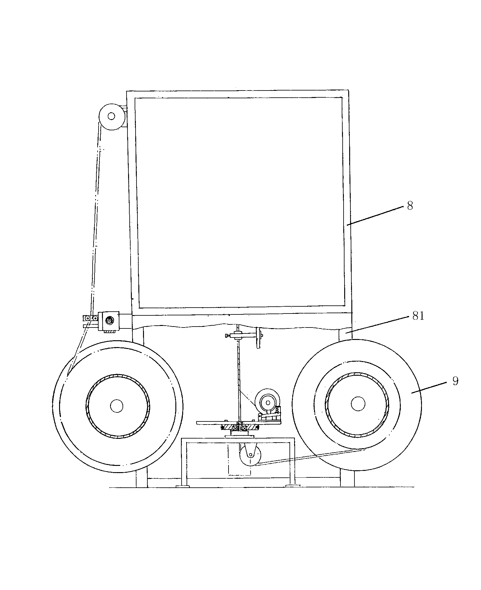
[0019] see figure 1 and combine figure 2 , the present invention is an active pay-off device for a braiding machine, the braiding machine includes a braiding machine body 8, and the active pay-off device includes a base 1, a front roller shaft 2, a rear roller shaft 3, and a pair of front bearing seats 4 and a pair of rear bearing seats 6, the base 1 is installed on the floor in front of the knitting machine body 8 in the use state, and the pair of front bearing seats 4 is installed on the base 1 and is close to the knitting machine body 8 is provided on one side, and a front rolling bearing 41 is respectively rotatably installed in a pair of front bearing seats 4, and both ends of the front roller shaft 2 are installed on the front rolling bearings 41 in a pair of front bearing seats 4. The pair of rear bearing seats 6 are installed on the base 1 and are arranged on the side away from the main body 8 of the knitting machine, and rear rolling bearings 61 are respectively ro...


PUM


Abstract

The invention relates to an active pay-off device for a knitting machine and belongs to the technical field of wire and cable production devices. The knitting machine comprises a knitting machine body, and the active pay-off device comprises a base, a front roll shaft, a rear roll shaft, a pair of front bearing blocks and a pair of rear bearing blocks. The base is installed on a floor in front of the knitting machine body, the pair of front bearing blocks is installed on the base and is close to one side of the knitting machine body, front rolling bearings are installed in the pair of front bearing blocks, the front roll shaft is installed on the pair of front rolling bearings, the pair of rear bearing blocks is installed on the base and is far away from one side of the knitting machine body, rear rolling bearings are installed in the pair of rear bearing blocks, and the rear roll shaft is installed on the pair of rear rolling bearings. The active pay-off device has the advantages that active pay-off is facilitated, constant pay-off tension is guaranteed, and thinning or deformation of a semi-finished product cable is avoided; the active pay-off device is simple in structure, saves energy and is environmentally friendly and low in production cost; installing and dismantling operation of a pay-off reel is simple, operation time is saved, and labor intensity is reduced; and the active pay-off device is suitable for pay-off reels of any size.

Description

technical field [0001] The invention belongs to the technical field of wire and cable production equipment, and in particular relates to an active wire releasing device for a braiding machine. Background technique [0002] The function of the wire and cable shielding sleeve braiding machine is to weave a metal mesh sleeve that is usually bare copper wire or tinned steel wire outside the semi-finished wire and cable. At present, the production of most metal mesh sleeves starts from paying off to taking up. Therefore, the pay-off device is an indispensable part of the cable production equipment. The convenience of loading and unloading the pay-off reel directly affects the efficiency of production. , and whether the pay-off device is durable is related to the maintenance cost of the equipment and whether continuous normal production can be guaranteed. The structure of the pay-off device varies according to the supporting equipment. The pay-off device on the traditional knitt...

Claims


Application Information

Patent Timeline
Patent Type & Authority Applications(China)
IPC IPC(8): B21F27/12B21F23/00
Inventor 邱建华周臆立沈云良
Owner SUZHOU CABLEPLUS PHOTOELECTRIC TECH
Why Eureka
Try Eureka