
electrostatic comb resonator

A resonator and comb-tooth technology, applied in the field of MEMS device design and manufacture, can solve problems such as affecting the normal operation of the resonator, structural warpage, etc., and achieve the effects of reducing thermal noise of resistance, improving sensitivity, and flexible wiring connection.

Active Publication Date: 2016-04-13
中科芯未来微电子科技成都有限公司
View PDF3 Cites 0 Cited by
  • Summary
  • Abstract
  • Description
  • Claims
  • Application Information

AI Technical Summary

Problems solved by technology

[0004] The existing resonator structures are generally micromechanical devices processed from bulk materials. The advantages of surface micromechanical technology are relatively low manufacturing costs, and it is also easy to achieve monolithic integration of MEMS and signal detection circuits. However, the release process Due to the stress mismatch of the materials in each layer, some structures will warp, which will affect the normal operation of the resonator.
The structure of the existing resonator generally includes a mass block provided with comb teeth, and the comb teeth are intersected with the electrodes. Since a row of comb teeth is connected to the mass block, the structure of the mass block is generally elongated; this structure causes the mass block to be The two ends are lifted due to the mismatch of stress, which affects the normal operation of the resonator in actual use

Method used


Image

  • electrostatic comb resonator
  • electrostatic comb resonator
  • electrostatic comb resonator

Examples


Embodiment Construction

[0029] The present invention will be further described below in conjunction with specific drawings.

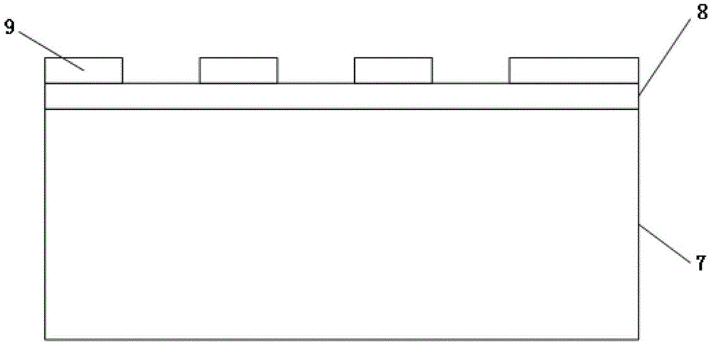
[0030] Such as figure 1 As shown, the electrostatic comb resonator of the present invention includes a substrate 7 and a structural layer on the substrate 7, and the structural layer includes an upper anchor point 1-1, a lower anchor point 1-2, a first interdigital capacitor 2-1, a second Second finger capacitor 2-2, third finger capacitor 2-3, fourth finger capacitor 2-4, upper elastic beam 3-1, lower elastic beam 3-2, vibrator mass, left anchor point 6-1 and the right anchor point 6-2, the left anchor point 6-1 and the right anchor point 6-2 are in the shape of a rectangular block, the upper anchor point 1-1 and the lower anchor point 1-2 are in the shape of a block; the quality of the vibrator The block includes a left mass block 4-1 and a right mass block 4-2, and the left mass block 4-1 and the right mass block 4-2 are connected by a connecting beam 5; the upper elastic ...


PUM


Abstract

The invention relates to an electrostatic comb resonator which comprises an upper anchor point, a lower anchor point, first interdigital capacitors, second interdigital capacitors, third interdigital capacitors, fourth interdigital capacitors, an upper elastic beam, a lower elastic beam, an oscillator mass block, a left anchor point and a right anchor point. The oscillator mass block comprises a left mass block and a right mass block. The electrostatic comb resonator is characterized in that the middle of the left side of the left mass block is sunken towards the right side of the left mass block to form a left groove, and the middle of the right side of the right mass block is sunken towards the left side of the right mass block to form a right groove; the first interdigital capacitors are arranged on the left side surfaces of the upper portion and the lower portion of the left mass block, and the second interdigital capacitors are arranged on the right side surfaces of the upper portion and the lower portion of the right mass block; the third interdigital capacitors are arranged at the left anchor point, and the fourth interdigital capacitors are arranged at the right anchor point; the first interdigital capacitors and the third interdigital capacitors are equidistantly configured in a crossed manner, and the second interdigital capacitors and the fourth interdigital capacitors are equidistantly configured in a crossed manner. The electrostatic comb resonator has the advantages that a potential hazard that the mass blocks are tilted to affect normal operation of the resonator is prevented, and accordingly a potential hazard that the mass blocks are tilted to affect the normal operation of the resonator in a manufacturing procedure is prevented.

Description

technical field [0001] The invention relates to an electrostatic comb-tooth resonator, in particular to an electrostatic comb-tooth resonator based on a CMOSDPTM (DoublePolyTripleMetal) mixed-signal process, and belongs to the technical field of design and manufacture of MEMS devices. Background technique [0002] With the development of science and technology, MEMS technology is more and more widely used in military and civilian applications. The mechanical vibration of the microstructure can be excited by many methods, such as: piezoelectricity, thermal expansion, electrostatic force and static magnetic force, and because the method of exciting by electrostatic force is simple, and the process is compatible with micromachining technology, so the electrostatic comb The resonator has become an important basic functional unit in MEMS. Electrostatic comb resonators have the advantages of being able to realize the conversion between mechanical energy and other energies, can ge...

Claims


Application Information

Patent Timeline
Patent Type & Authority Patents(China)
IPC IPC(8): H03H9/24H03H3/007B81B7/00
Inventor 薛惠琼王玮冰田龙坤
Owner 中科芯未来微电子科技成都有限公司
Learn More