Electromagnetic relay

A technology of electromagnetic relay and electromagnetic block, applied in the direction of electromagnetic relay, relay, detailed information of electromagnetic relay, etc., can solve the problem of difficulty in ensuring the attractive force of electromagnet, and achieve the effect of preventing the deterioration of operation performance

Active Publication Date: 2013-09-18
OMRON CORP
View PDF5 Cites 4 Cited by
  • Summary
  • Abstract
  • Description
  • Claims
  • Application Information

AI Technical Summary

Problems solved by technology

As a result, it is difficult to ensure the required attractive force of the electromagnet, which makes it difficult to miniaturize the conventional electromagnetic relay

Method used


Image

  • Electromagnetic relay
  • Electromagnetic relay
  • Electromagnetic relay

Examples


Embodiment Construction

[0023] Hereinafter, preferred embodiments of the present invention will be described with reference to the accompanying drawings. Note that in the following description, terms referring to specific directions and positions (for example, terms including 'upper', 'lower', 'side' and 'end') are used if necessary. The purpose of using those terms is to help people better understand the present invention with reference to the accompanying drawings, however, the technical scope of the present invention should not be limited by the meanings of those terms. The following description represents only a basic example of the invention, and is not intended to limit the invention, the application of the invention, and the use of the invention.

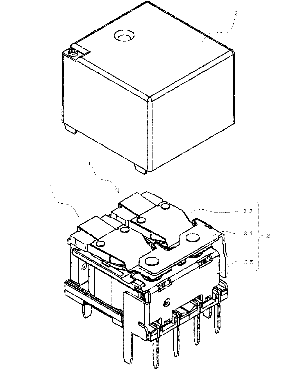
[0024] figure 1 An electromagnetic relay according to an embodiment of the present invention is shown. The electromagnetic relay is configured such that a pair of electromagnetic blocks 1 are arranged side by side, a contact switch mechanism 2 is ...


PUM


Abstract

Provided is an electromagnetic relay which can sufficiently dissipate heat generated from a coil to secure desired attracting force even when the electromagnetic relay is miniaturized. The electromagnetic relay includes an electromagnet block and a contact switching mechanism. A movable contact piece of the contact switching mechanism includes a contact attaching portion to which a movable contact is attached, and a first fixed portion attached to a first movable iron piece of the electromagnet block. The first fixed portion is in surface contact with the movable iron piece and is substantially equal in width dimension to the movable iron piece.

Description

technical field [0001] The invention relates to an electromagnetic relay. Background technique [0002] Conventionally, as an electromagnetic relay, there is known an electromagnetic relay having a structure in which a fixed terminal is locked and attached to each bobbin of each electromagnetic block in a press-fit manner, and each The two flanges are connected in parallel with each other so that the electromagnetic blocks can be integrally combined (for example, see Japanese Unexamined Patent Publication No. 2000-315448). [0003] However, in such a conventional electromagnetic relay, when miniaturizing the electromagnetic relay, it is necessary to reduce the width dimension of the movable contact piece due to its structural characteristics. This also causes a reduction in the size of the electromagnet. Therefore, in order to secure the same magnitude of attractive force with a reduced-sized electromagnet, it is necessary to increase the amount of current flow to the coil...

Claims


Application Information

Patent Timeline
Patent Type & Authority Applications(China)
IPC IPC(8): H01H51/01H01H50/54
CPCH01H50/58H01H50/60H01H51/20H01H45/12
Inventor 小林正树
Owner OMRON CORP
Why Eureka
Try Eureka