
Touch control pen

A technology of stylus and pen holder, which is applied in the direction of instruments, electrical digital data processing, and the input/output process of data processing, etc. It can solve problems such as unsmooth hand feel and increase manufacturing cost, and achieve smoothness and flexibility. manipulative effect

Inactive Publication Date: 2013-09-18
CORETRONIC
View PDF4 Cites 4 Cited by
  • Summary
  • Abstract
  • Description
  • Claims
  • Application Information

AI Technical Summary

Problems solved by technology

In order to enable the nib to trigger the switch smoothly under various force conditions, some known stylus increases the number of switches on the circuit board, but this will increase the manufacturing cost, and the user will not be able to use the stylus when using the stylus. It is easy to produce an unsmooth feel due to the switching of different switches

Method used


Image

  • Touch control pen
  • Touch control pen
  • Touch control pen

Examples


Embodiment Construction

[0036] The foregoing and other technical contents, features and effects of the present invention will be clearly presented in the following detailed description of multiple embodiments with reference to the accompanying drawings. The directional terms mentioned in the following embodiments, such as "upper", "lower", "front", "rear", "left", "right", etc., are only referring to the directions of the drawings. Accordingly, the directional terms are used to illustrate, not to limit, the invention.

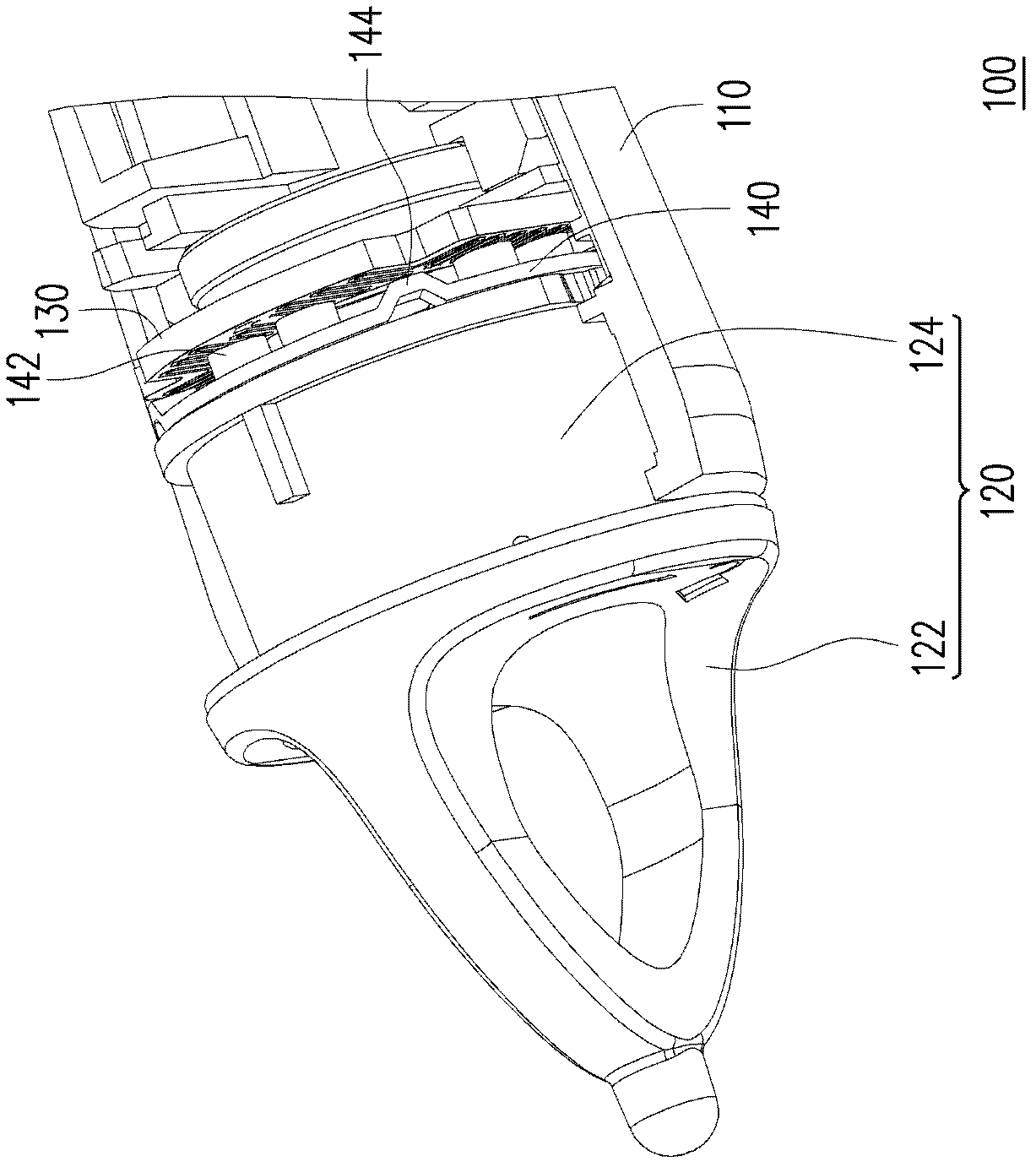
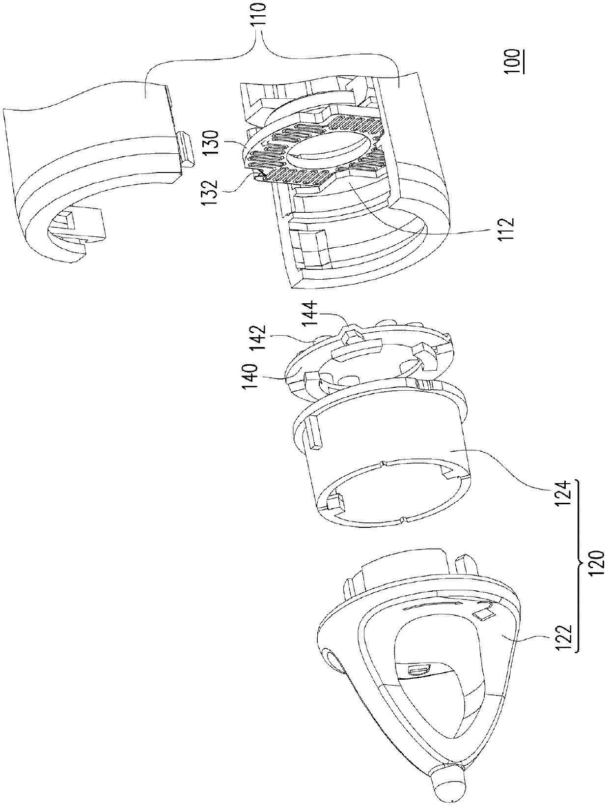
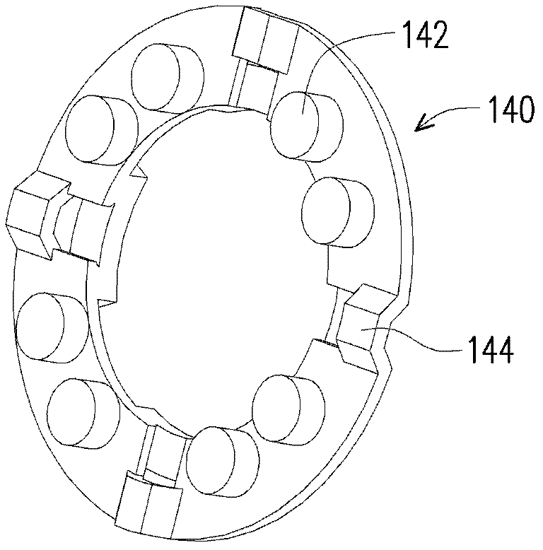
[0037] figure 1 It is a partial perspective view of a stylus according to an embodiment of the present invention. figure 2 for figure 1 An exploded view of the stylus. image 3 for figure 1 A perspective view of an elastic conductor. Please refer to Figure 1 to Figure 3 , the stylus 100 of this embodiment includes a pen shaft 110 , a pen head 120 , a circuit board 130 and an elastic conductor 140 . The pen tip 120 is disposed at one end of the pen barrel 110 . The circuit bo...


PUM


Abstract

The invention relates to a touch control pen, which comprises a pen holder, a pen head, a circuit board, a signal emitting unit and an elastic conductor, wherein the pen head is arranged at one end of the pen holder, the circuit board is arranged in the pen holder and is provided with a circuit layer, the signal emitting unit is arranged in the pen holder and is electrically connected with the circuit board, the elastic conductor is arranged between the pen head and the circuit board and is provided with a plurality of convex points, and the positions of the convex points correspond to the circuit layer. When the pen head pushes the elastic conductor, and any one convex point in the convex points is in contact with the circuit layer, the circuit layer is conducted by the elastic conductor, and the signal emitting unit is driven to emit a signal to a protector.

Description

technical field [0001] The invention relates to a touch pen, and in particular to a touch pen applied to a projection device. Background technique [0002] A projection device is a display device for producing large-scale images. The imaging principle of the projection device is to convert the illumination beam generated by the light source into an image beam through a light valve, and then convert the image beam into a projection beam through a lens, and project it onto a screen or a wall. With the advancement of projection technology and the reduction of manufacturing costs, the use of projection devices has gradually expanded from commercial use to home use. [0003] In order to allow users to write or mark on the screen projected by the projector, an interactive touch pen has been developed. The user can use the interactive stylus to write on the projection surface. When the nib of the stylus is pushed against the switch on the circuit board inside the stylus, the styl...

Claims


Application Information

Patent Timeline
IPC IPC(8): G06F3/0354
Inventor 陈彦维林建戌
Owner CORETRONIC
Learn More