
Laser optical electric axis power measuring probe

A technology for measuring probe and shaft power, applied in power metering, measuring device, torque metering and other directions, it can solve the problems affected by complex environmental factors, difficult installation and maintenance of strain gauges, unsatisfactory measurement results, etc., to improve maintainability. performance, convenient operation and maintenance, and compact structure

Active Publication Date: 2013-09-18
WUHAN UNIV OF TECH
View PDF3 Cites 2 Cited by
  • Summary
  • Abstract
  • Description
  • Claims
  • Application Information

AI Technical Summary

Problems solved by technology

Although the current relatively advanced shaft power monitoring device uses a telemetry strain gauge, the measurement effect is still unsatisfactory. In addition, the installation and maintenance of the strain gauge is difficult and it is easily affected by complex environmental factors. The performance is not stable enough, and the measurement results are not satisfactory. Accurate, requires regular calibration
Non-contact measurement is the future development direction of shafting power and torsion measurement. At present, there are mainly magnetoelastic measurement method and laser Doppler measurement method. The former is measured according to the magnetoelastic effect, but its effect depends to a large extent It depends on the material properties and processing technology of the shaft; the latter is measured based on laser Doppler technology and optical heterodyne principle, but the error caused by the temperature drift of the photoelectric measurement sensor cannot be avoided

Method used


Image

  • Laser optical electric axis power measuring probe
  • Laser optical electric axis power measuring probe
  • Laser optical electric axis power measuring probe

Examples


Embodiment Construction

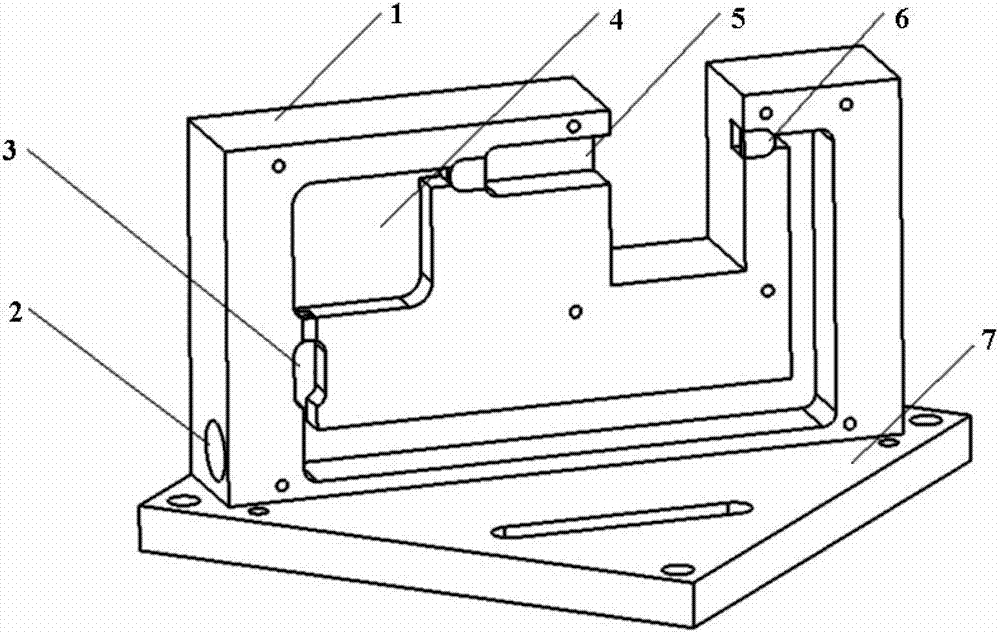
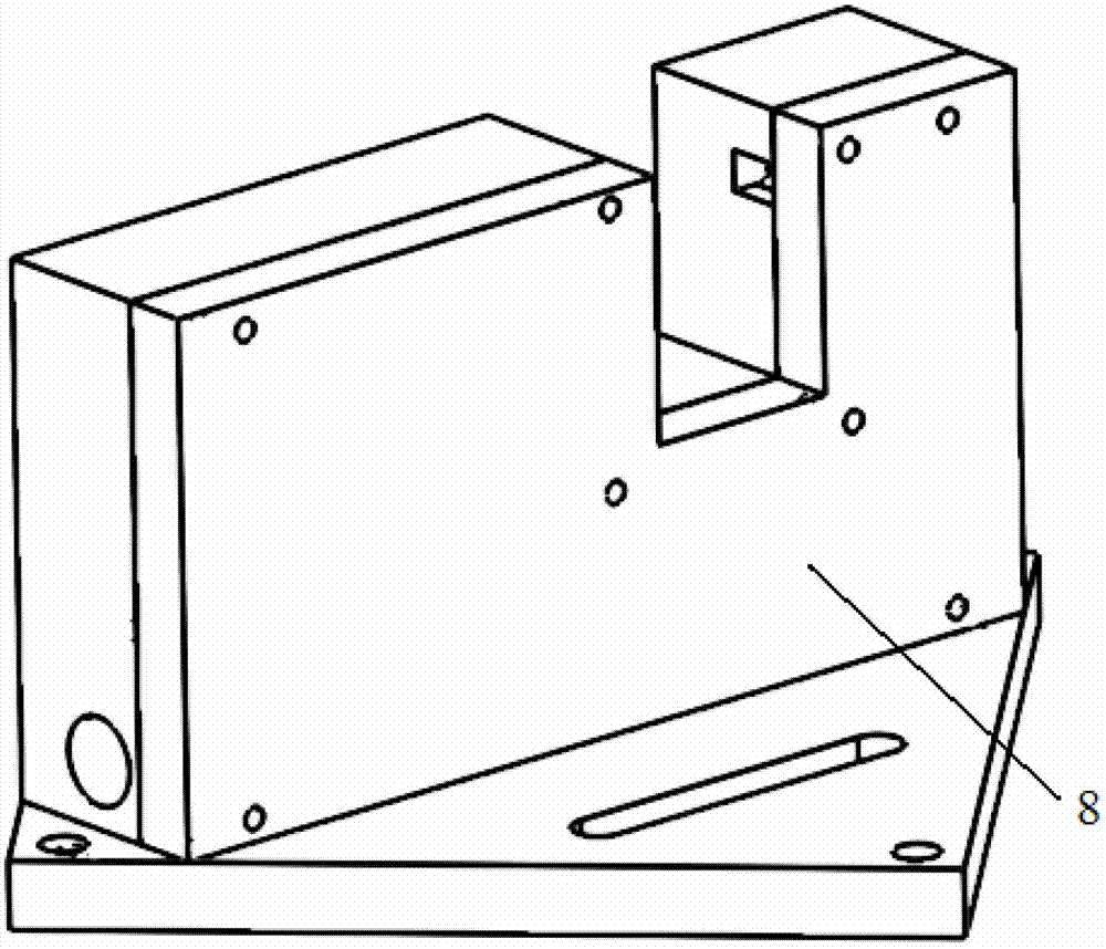
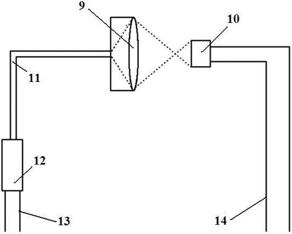
[0028] The laser photoelectric axial power measurement probe of the present invention adopts the structure of optical fiber + laser diode + optical fiber focusing mirror + photoelectric detector, and integrates all components into the inside of the sensor probe, no longer needs to use optical fiber outside the probe, and only uses a short The distance is fixed to the optical fiber, and the external cable is connected to the power supply and the electrical signal to the controller through a waterproof aviation plug. The entire probe shell is designed to be waterproof and dustproof to meet the use requirements in harsh environments.

[0029] The present invention will be further described below in conjunction with the embodiments and accompanying drawings, but the content of the present invention is not limited.

[0030] The laser photoelectric shaft power measurement probe applied to the non-contact photoelectric shaft power measurement device provided by the present invention h...


PUM


Abstract

The invention relates to a laser optical electric axis power measuring probe. The probe mainly comprising a measuring probe optical chamber (1), an optical fiber focus lens (9), an optical electric diode (10) and a laser diode (12); the measuring probe optical chamber (1) is provided with a fixing slot which contains and fixes the optical fiber focus lens (9), the optical electric diode (10) and the laser diode (12), wherein the optical fiber focus lens (9) and the laser diode (12) are connected by an optical fiber. The measuring probe provided by the invention has the following advantages that the probe has integrated structure, therefore the mounting space is saved; by adopting the embedded structure, the optical fiber is convenient to mount; through collecting laser by using the optical fiber focus lens, the measuring accuracy is enhanced; and the whole probe has the advantages of being waterproof and dust proof, being free from the affect of working environment and the like.

Description

technical field [0001] The invention relates to a part of a measuring device, in particular to a laser photoelectric shaft power measurement probe suitable for photoelectric non-contact shaft power measurement, which is suitable for applications such as monitoring the working condition of a shaft system. Background technique [0002] In ship navigation, the propulsion shafting is an important part to realize the energy transfer between the ship's main engine and the propeller (generally the propeller), and it is an indispensable and important part of the ship's power plant system. With the development of ships in the direction of large-scale, high-speed and automation, higher requirements are put forward for the safety and reliability of propulsion shafting. By monitoring the operating status of the ship's power system online in real time, and judging whether there is a fault and the severity of the fault, the reliability of the ship's power system can be improved. At the s...

Claims


Application Information

Patent Timeline
IPC IPC(8): G01L3/24
Inventor 杨琨谈微中严新平王磊余舒周新聪
Owner WUHAN UNIV OF TECH
Learn More